4 RECORDING YOUR CONNECTIONS
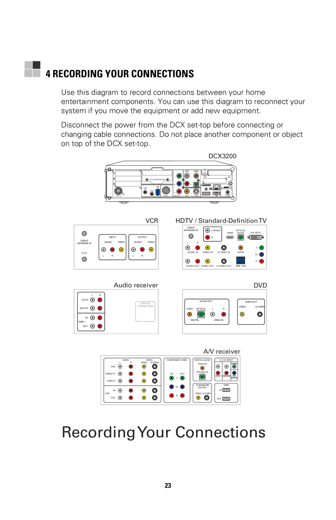
Use this diagram to record connections between your home entertainment components. You can use this diagram to reconnect your system if you move the equipment or add new equipment.
Disconnect the power from the DCX
DCX3200
|
|
| AUDIO |
| DIGITAL |
|
|
| OUT |
| AUDIO |
|
| Y |
| L | 5 |
|
|
|
|
| |
|
| Pb |
| R |
|
EXT IR | IEEE |
|
|
|
|
1394 |
|
|
|
| |
IN |
|
|
|
|
|
| SERIAL |
|
|
|
|
|
| Pr |
|
|
|
CABLE IN | RF OUT | VIDEO OUT | VIDEO |
|
4![]()
POWER +12 VDC
|
|
|
|
| VCR |
| INPUT |
|
| OUTPUT | |
CABLE/ | AUDIO | VIDEO |
| AUDIO | VIDEO |
ANTENNA IN |
| ||||
|
|
|
|
| |
ToTV |
|
|
|
|
|
L | R |
| L | R |
|
HDTV /
CABLE/ |
|
|
|
ANTENNA IN | L/MONO | OPTICAL | |
| HDMI | SPDIF |
R
LR
|
|
| Y |
AUDIO IN | VIDEO IN | SPDIF | |
|
|
| Pb |
|
|
| Pr |
AUDIO OUT | VIDEO OUT | IEEE 1394 |
Audio receiver
LR
CD IN ![]()
![]()
SPEAKER
CONNECTORS
AUX IN
IN
TAPE 1
OUT
DVD
AUDIO OUT | VIDEO OUT |
VIDEO
COAX | OPTICAL | L | R |
DIGITAL |
| ANALOG | |
A/V receiver
| AUDIO | VIDEO | COMPONENT VIDEO | DIGITAL AUDIO | 5.1 CH INPUT | |
L | R | VIDEO |
|
| COAX IN | CENTER |
|
|
|
|
| ||
DVD |
|
|
|
|
| L |
CABLE/TV |
|
| IN | OUT | OPTICAL IN | R |
|
|
|
| |||
|
|
|
|
|
| FRONT SURROUND SUB- |
|
|
|
| Y |
| WOOFER |
VIDEO 2 |
|
|
|
|
|
|
|
|
|
| Pb | TV/MONITOR | HDMI |
|
|
|
| OUTPUT | IN | |
IN |
|
|
|
|
| |
VCR |
|
|
|
| VIDEO |
|
Pr
OUT
OUT
RecordingYour Connections
23