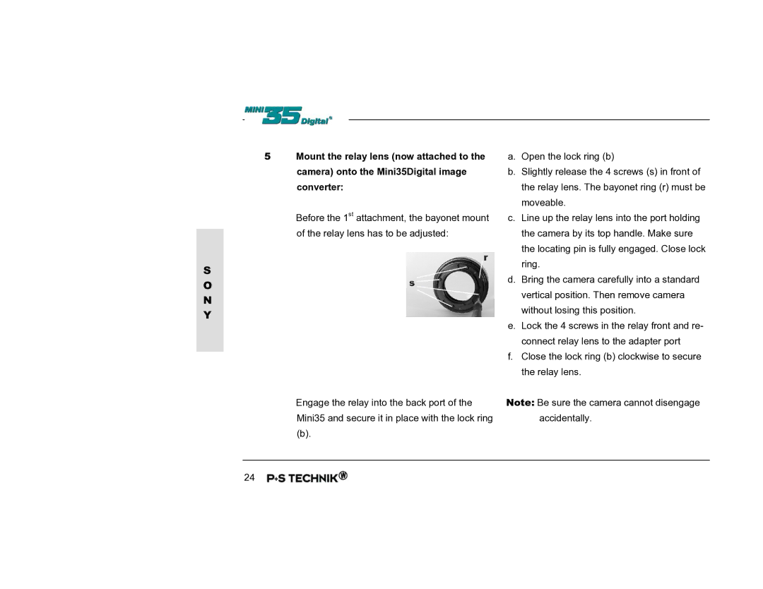
5 | Mount the relay lens (now attached to the | a. Open the lock ring (b) | |
|
| camera) onto the Mini35Digital image | b. Slightly release the 4 screws (s) in front of |
|
| converter: | the relay lens. The bayonet ring (r) must be |
|
|
| moveable. |
|
| Before the 1st attachment, the bayonet mount | c. Line up the relay lens into the port holding |
|
| of the relay lens has to be adjusted: | the camera by its top handle. Make sure |
|
| ||
|
|
| the locating pin is fully engaged. Close lock |
S |
|
| ring. |
|
| d. Bring the camera carefully into a standard | |
O |
|
| |
|
| vertical position. Then remove camera | |
N |
|
| |
|
| without losing this position. | |
Y |
|
| |
|
| e. Lock the 4 screws in the relay front and re- | |
|
|
| |
|
|
| connect relay lens to the adapter port |
|
|
| f. Close the lock ring (b) clockwise to secure |
|
|
| |
|
|
| the relay lens. |
Engage the relay into the back port of the Mini35 and secure it in place with the lock ring
(b).
Note: Be sure the camera cannot disengage accidentally.
24
