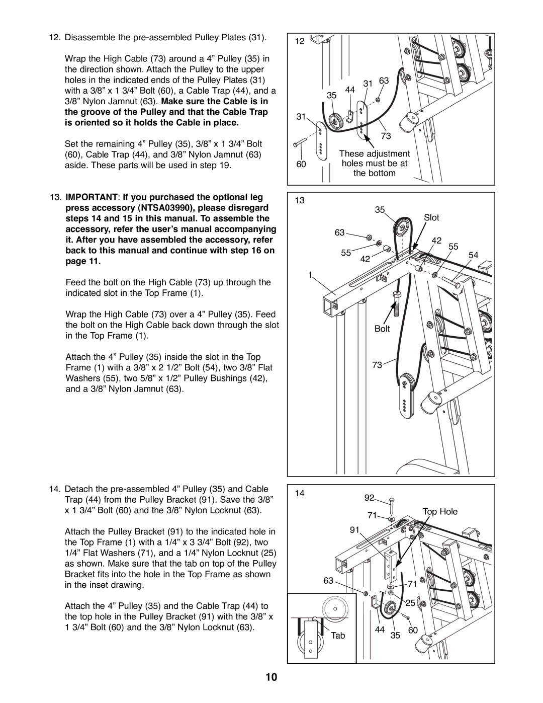
12.Disassemble the
Wrap the High Cable (73) around a 4Ó Pulley (35) in the direction shown. Attach the Pulley to the upper holes in the indicated ends of the Pulley Plates (31) with a 3/8Ó x 1 3/4Ó Bolt (60), a Cable Trap (44), and a 3/8Ó Nylon Jamnut (63). Make sure the Cable is in the groove of the Pulley and that the Cable Trap is oriented so it holds the Cable in place.
Set the remaining 4Ó Pulley (35), 3/8Ó x 1 3/4Ó Bolt (60), Cable Trap (44), and 3/8Ó Nylon Jamnut (63) aside. These parts will be used in step 19.
13.IMPORTANT: If you purchased the optional leg press accessory (NTSA03990), please disregard steps 14 and 15 in this manual. To assemble the accessory, refer the userÕs manual accompanying it. After you have assembled the accessory, refer back to this manual and continue with step 16 on page 11.
Feed the bolt on the High Cable (73) up through the indicated slot in the Top Frame (1).
Wrap the High Cable (73) over a 4Ó Pulley (35). Feed the bolt on the High Cable back down through the slot in the Top Frame (1).
Attach the 4Ó Pulley (35) inside the slot in the Top Frame (1) with a 3/8Ó x 2 1/2Ó Bolt (54), two 3/8Ó Flat Washers (55), two 5/8Ó x 1/2Ó Pulley Bushings (42), and a 3/8Ó Nylon Jamnut (63).
14.Detach the
Attach the Pulley Bracket (91) to the indicated hole in the Top Frame (1) with a 1/4Ó x 3 3/4Ó Bolt (92), two 1/4Ó Flat Washers (71), and a 1/4Ó Nylon Locknut (25) as shown. Make sure that the tab on top of the Pulley Bracket fits into the hole in the Top Frame as shown in the inset drawing.
Attach the 4Ó Pulley (35) and the Cable Trap (44) to the top hole in the Pulley Bracket (91) with the 3/8Ó x 1 3/4Ó Bolt (60) and the 3/8Ó Nylon Locknut (63).
10
12 |
|
|
|
| 31 | 63 |
|
35 | 44 |
|
|
31 |
|
|
|
|
| 73 |
|
| These adjustment |
| |
60 | holes must be at |
| |
| the bottom |
| |
13 |
| 35 |
|
|
|
| |
|
| Slot |
|
63 | 42 |
| |
| 55 | 55 | |
|
| 54 | |
| 42 |
|
|
1 |
|
|
|
|
| Bolt |
|
| 73 |
| |
14 | 92 |
|
|
|
|
| |
| 71 |
| Top Hole |
|
|
| |
| 91 |
|
|
63 |
|
| 71 |
|
|
| |
|
|
| 25 |
Tab | 44 | 35 | 60 |