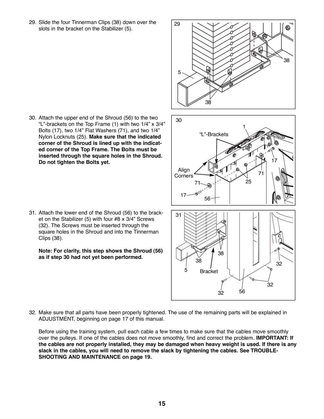
29.Slide the four Tinnerman Clips (38) down over the slots in the bracket on the Stabilizer (5).
30.Attach the upper end of the Shroud (56) to the two
31.Attach the lower end of the Shroud (56) to the brack- et on the Stabilizer (5) with four #8 x 3/4Ó Screws (32). The Screws must be inserted through the square holes in the Shroud and into the Tinnerman Clips (38).
Note: For clarity, this step shows the Shroud (56) as if step 30 had not yet been performed.
29 |
|
|
|
| 38 |
5 |
|
|
| 38 |
|
30 |
|
|
|
| 1 |
|
| |
|
| 17 |
Align |
| 71 |
Corners |
| |
| 25 | |
| 71 | |
17 | 56 |
|
|
| |
31 |
|
|
| 38 |
|
| 38 | 32 |
|
| |
5 | Bracket |
|
|
| 32 |
| 32 | 56 |
32.Make sure that all parts have been properly tightened. The use of the remaining parts will be explained in ADJUSTMENT, beginning on page 17 of this manual.
Before using the training system, pull each cable a few times to make sure that the cables move smoothly over the pulleys. If one of the cables does not move smoothly, find and correct the problem. IMPORTANT: If the cables are not properly installed, they may be damaged when heavy weight is used. If there is any slack in the cables, you will need to remove the slack by tightening the cables. See TROUBLE- SHOOTING AND MAINTENANCE on page 19.
15