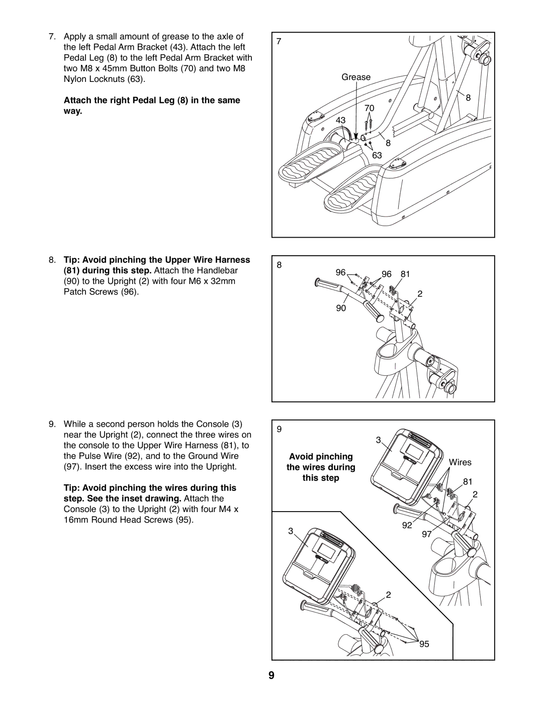
7. Apply a small amount of grease to the axle of | 7 |
|
|
the left Pedal Arm Bracket (43). Attach the left |
|
| |
|
|
| |
Pedal Leg (8) to the left Pedal Arm Bracket with |
|
|
|
two M8 x 45mm Button Bolts (70) and two M8 | Grease |
| |
Nylon Locknuts (63). |
| ||
Attach the right Pedal Leg (8) in the same |
| 70 | 8 |
way. | 43 |
| |
|
|
| |
|
| 8 |
|
|
| 63 |
|
8. Tip: Avoid pinching the Upper Wire Harness | 8 |
|
|
(81) during this step. Attach the Handlebar |
|
| |
96 | 96 | 81 | |
(90) to the Upright (2) with four M6 x 32mm |
|
|
|
Patch Screws (96). |
|
| 2 |
| 90 |
|
|
9. While a second person holds the Console (3) | 9 |
| |
near the Upright (2), connect the three wires on |
| ||
| 3 | ||
the console to the Upper Wire Harness (81), to |
| ||
|
| ||
the Pulse Wire (92), and to the Ground Wire | Avoid pinching | Wires | |
(97). Insert the excess wire into the Upright. | the wires during | ||
| |||
Tip: Avoid pinching the wires during this | this step | 81 | |
| |||
| 2 | ||
step. See the inset drawing. Attach the |
| ||
|
| ||
Console (3) to the Upright (2) with four M4 x |
|
| |
16mm Round Head Screws (95). |
| 92 | |
| 3 | ||
| 97 | ||
|
| ||
|
| 2 | |
|
| 95 | |
| 9 |
|
