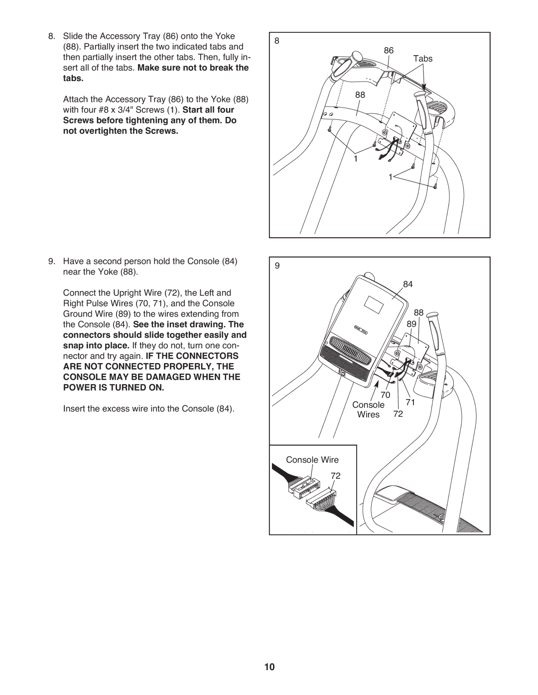
8. Slide the Accessory Tray (86) onto the Yoke | 8 |
|
|
|
(88). Partially insert the two indicated tabs and | 86 |
| ||
then partially insert the other tabs. Then, fully in- |
| Tabs | ||
sert all of the tabs. Make sure not to break the |
|
|
| |
tabs. |
| 88 |
|
|
Attach the Accessory Tray (86) to the Yoke (88) |
|
|
| |
with four #8 x 3/4" Screws (1). Start all four |
|
|
|
|
Screws before tightening any of them. Do |
|
|
|
|
not overtighten the Screws. |
| 1 |
|
|
|
|
|
| |
|
| 1 |
|
|
9. Have a second person hold the Console (84) | 9 |
|
|
|
near the Yoke (88). |
|
| 84 | |
Connect the Upright Wire (72), the Left and |
|
|
| |
Right Pulse Wires (70, 71), and the Console |
|
|
| 88 |
Ground Wire (89) to the wires extending from |
|
|
| |
the Console (84). See the inset drawing. The |
|
|
| 89 |
connectors should slide together easily and |
|
|
|
|
snap into place. If they do not, turn one con- |
|
|
|
|
nector and try again. IF THE CONNECTORS |
|
|
|
|
ARE NOT CONNECTED PROPERLY, THE |
|
|
|
|
CONSOLE MAY BE DAMAGED WHEN THE |
|
|
|
|
POWER IS TURNED ON. |
| 70 |
| 71 |
Insert the excess wire into the Console (84). |
| Console | 72 | |
| Wires |
| ||
|
| Console Wire |
|
|
|
| 72 |
|
|
| 10 |
|
|
|
