Reinstalling the Burner Assembly:

1.Reinstall the gas manifold assembly to the burner box with the four (4) fasteners, which were removed earlier.

2.Carefully reinstall the burner box into the unit. After installing the burner, inspect the alignment of the burners with the heat exchanger tubes. The center of the burn- ers should be aligned with the center of the tubes.

3.Reconnect the gas piping to the gas valve.

4.Reconnect the wires to the gas valve termi- nals.

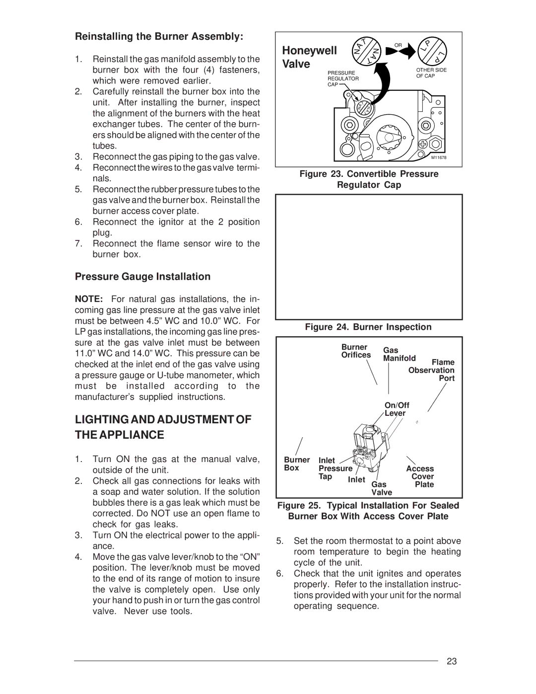
5.Reconnect the rubber pressure tubes to the gas valve and the burner box. Reinstall the burner access cover plate.

6.Reconnect the ignitor at the 2 position plug.

7.Reconnect the flame sensor wire to the burner box.

Pressure Gauge Installation

NOTE: For natural gas installations, the in- coming gas line pressure at the gas valve inlet must be between 4.5” WC and 10.0” WC. For LP gas installations, the incoming gas line pres- sure at the gas valve inlet must be between 11.0” WC and 14.0” WC. This pressure can be checked at the inlet end of the gas valve using a pressure gauge or U-tube manometer, which must be installed according to the manufacturer’s supplied instructions.

LIGHTING AND ADJUSTMENT OF THE APPLIANCE

1.Turn ON the gas at the manual valve, outside of the unit.

2.Check all gas connections for leaks with a soap and water solution. If the solution bubbles there is a gas leak which must be corrected. Do NOT use an open flame to check for gas leaks.

3.Turn ON the electrical power to the appli- ance.

4.Move the gas valve lever/knob to the “ON” position. The lever/knob must be moved to the end of its range of motion to insure the valve is completely open. Use only your hand to push in or turn the gas control valve. Never use tools.

Honeywell

A

T


N

OR

L

P


N


L

Valve


T

A


P


OTHER SIDE

PRESSURE


OF CAP


REGULATOR


CAP


A

T

N


N


T

A


M11678

Figure 23. Convertible Pressure

Regulator Cap

Figure 24. Burner Inspection


Burner

Gas


Orifices


Manifold

Flame


Observation


Port


On/Off


Lever


Burner

Inlet


Box

Pressure


Access


Tap

Inlet


Cover


Gas

Plate


Valve


Figure 25. Typical Installation For Sealed

Burner Box With Access Cover Plate

5.Set the room thermostat to a point above room temperature to begin the heating cycle of the unit.

6.Check that the unit ignites and operates properly. Refer to the installation instruc- tions provided with your unit for the normal operating sequence.

23

Page 23
Image 23
Nordyne M3RL installation instructions Lighting and Adjustment of the Appliance, Convertible Pressure Regulator Cap

M3RL specifications

The Nordyne M3RL is a high-efficiency gas furnace designed for residential heating applications, characterized by its robust performance and advanced technologies. It is part of Nordyne's distinguished lineup, which emphasizes reliability and comfort in home heating systems. The M3RL model is particularly notable for its focus on energy efficiency, making it an attractive option for homeowners looking to reduce their energy expenses while maintaining optimal heating levels.

One of the standout features of the Nordyne M3RL is its high Annual Fuel Utilization Efficiency (AFUE) rating, which often exceeds 80%. This efficient design ensures that more of the fuel consumed is converted into usable heat for the home. By employing a variable-speed blower, the M3RL enhances comfort by allowing for more precise control over air circulation, contributing to better temperature consistency throughout the living space.

The M3RL utilizes advanced multi-stage heating technology, allowing the system to operate at different capacities depending on the heating demand. This means it can run at lower settings during milder weather, which not only saves energy but also reduces wear and tear on the equipment, extending its lifespan. The furnace also includes a reliable ignition system that ensures quick and safe starts, eliminating the inefficiencies associated with older pilot light systems.

Another important characteristic of the Nordyne M3RL is its acoustical insulation, which minimizes operational noise. The quiet operation is particularly valued in residential settings, where noise pollution can be disruptive. Additionally, the furnace features a compact design, making it easy to install in a variety of spaces, including tight basements or utility rooms.

The M3RL model is also equipped with a smart control system that interfaces seamlessly with modern thermostats, offering homeowners the ability to program their heating schedules and optimize energy usage. This integration with smart home technology positions the M3RL not just as a heating solution, but as a component of a more comprehensive home energy management system.

In conclusion, the Nordyne M3RL gas furnace represents a blend of efficiency, advanced technology, and user-friendly features. Its high AFUE rating, multi-stage heating capability, quiet operation, and smart technology integration make it a reliable choice for homeowners aiming to enhance their comfort while minimizing energy costs. This furnace is a testament to Nordyne's commitment to innovation in the HVAC industry.