X |
| FROM | |
|
| ||
W3 | (Optional,Check | BLOWER | |
Thermostat | RELAY | ||
|
Instructions)
ECONOMIZER | W2 |
PLUG | Green |
Y2 |
X |
| FROM | |
|
| ||
W3 | (Optional,Check | BLOWER | |
RELAY | |||
Thermostat | |||
| |||
W2 | Instructions) |
| |
| Green | ||
ECONOMIZER |
|
1
2Y1
3
4R
Blue 5
6G
7
8O
9![]()
E
INDOOR
THERMOSTAT
![]() C
C
![]() Y
Y
![]() O
O
![]() W2
W2
![]() R
R
E
DEFROST
BOARD
PLUG | Y2 |
| |
|
| ||
1 | Y1 |
| |
2 |
| ||
| C | ||
3 | R | ||
4 |
| ||
| Y | ||
Blue 5 |
| ||
G |
| ||
6 |
| ||
| O | ||
7 |
| ||
O |
| ||
8 | W2 | ||
| |||
9 |
| ||
E |
| ||
| R | ||
|
| ||
| INDOOR | E | |
|
| ||
| THERMOSTAT | DEFROST | |
| |||
| BOARD | ||
|
|
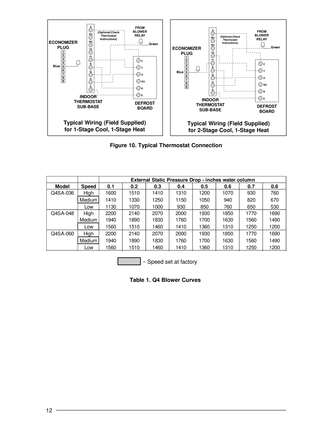
Typical Wiring (Field Supplied) for
Typical Wiring (Field Supplied) for
Figure 10. Typical Thermostat Connection
|
|
|
| External | Static | Pressure Drop - inches water | column |
| ||
Model | Speed | 0.1 | 0.2 | 0.3 | 0.4 | 0.5 | 0.6 | 0.7 | 0.8 | |
High | 1600 | 1510 | 1410 | 1310 | 1200 | 1070 | 930 | 760 | ||
| Medium | 1410 | 1330 | 1250 | 1150 | 1050 | 940 | 820 | 670 | |
| Low | 1130 | 1070 | 1000 | 930 | 850 | 760 | 650 | 530 | |
High | 2200 | 2140 | 2070 | 2000 | 1930 | 1850 | 1770 | 1690 | ||
| Medium |
| 1940 | 1890 | 1830 | 1760 | 1700 | 1630 | 1560 | 1490 |
| Low |
| 1560 | 1510 | 1460 | 1410 | 1360 | 1310 | 1250 | 1200 |
High | 2200 | 2140 | 2070 | 2000 | 1930 | 1850 | 1770 | 1690 | ||
| Medium | 1940 | 1890 | 1830 | 1760 | 1700 | 1630 | 1560 | 1490 | |
| Low | 1560 | 1510 | 1460 | 1410 | 1360 | 1310 | 1250 | 1200 | |
![]()
![]() - Speed set at factory
- Speed set at factory
Table 1. Q4 Blower Curves
12
