NHTC NORTEC LINKS 2 OPTIONS Installation Manual
Manual No. H-502
RECORD OF REVISIONS
PROPRIETARY NOTICE
LIABILITY NOTICE
COPYRIGHT NOTICE
WARRANTY
TABLE OF CONTENTS
10-10INSTALLATION PROCEDURES
10-30TROUBLESHOOTING
LIST OF FIGURES
LIST OF TABLES
10-10INSTALLATION
2008-02-18
THIS PAGE INTENTIONALLY LEFT BLANK
Page
10-00 INTRODUCTION
10-00
10-00
1OVERVIEW
Protocol Options
Page
10-10 INSTALLATION
10-10
10-10
1NETWORKING
BBACNET/IP
2WIRING
Table 1. Recommended Wire Types and Lengths
ABACNET/MSTP, JOHNSON N2, AND LONWORKS
ALONWORKS.XIF FILE
3 GATEWAY CONFIGURATION
4NETWORK INTEGRATION
Table 2. Baud Rates
Page
5 VARIABLE DEFINITION
10-10
Unit must be configured for
Variable Definitions
Unit must be configured for dual
Page
10-10
Default Johnson N2 Address
Table 4. Humidifier Variable Addresses Unit #1
Default BACnet/IP Address 192.168.10.11 Subnet
Default BACnet/MSTP Address
Page
Table 5. Humidifier Variable Addresses Unit #2
10-10
Page
Table 6. Humidifier Variable Addresses Unit #3
10-10
Page
Table 7. Humidifier Variable Addresses Unit #4
10-10
Page
Table 8. Humidifier Variable Addresses Unit #5
10-10
Page
Table 9. Humidifier Variable Addresses Unit #6
10-10
Page 14
Table 10. Humidifier Variable Addresses Unit #7
10-10
Page
Table 11. Humidifier Variable Addresses Unit #8
10-10
Figure 2. Sample Humidification Applications
NHTC
Figure 1. Sample Humidification Applications
Room-Sensed%RH Feedback with Duct Hi-LimitSensing
Page
Figure 3. Sample Humidification Applications
10-10
NHTC
Page
THIS PAGE INTENTIONALLY LEFT BLANK
10-10
Page
10-20 START-UP
10-20
10-20
1 NORTEC LINKS 2 START-UPCHECKLIST
2 START-UPPROCEDURE
Page
10-30 TROUBLESHOOTING
10-30
10-30
1TROUBLESHOOTING
2INDICATOR LIGHTS
Figure 3. LonWorks Module LED
Figure 1. OnLine Diagnostic LED Locations
10-30
Figure 2. BACnet Module LED
LED Name
Table 1. OnLine Diagnostic LED Description
10-30
Page
LED Name
Table 2. LINKS 2 Module Diagnostic LEDs
10-30
Page
10-30
Table 3. Troubleshooting Communication Problems
Problem
Solution
Page
10-40 SPARE PARTS
10-40
Part Number
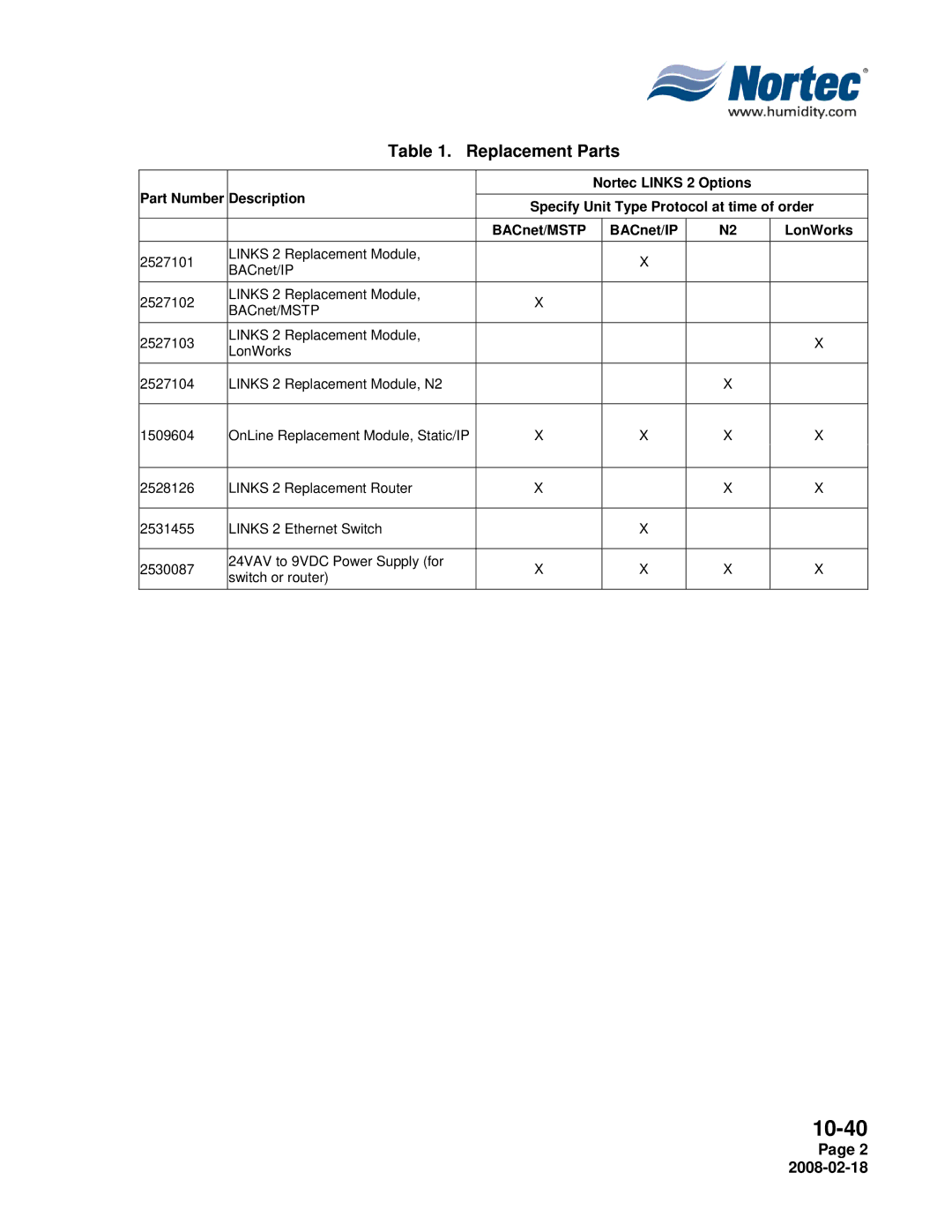
Table 1. Replacement Parts
10-40
Page
Page
10-40
Figure 1. BACnet or N2 Module
Figure 3. OnLine Module
Page
Figure 5. Ethernet Switch
10-40
Page
10-50 TECHNICAL
10-50
Supplemental Wiring Diagram
Net + Net
DC Power
Switch
Figure 2. Wiring Diagram
Net + Net
DC Power Supply
Supplemental Wiring Diagram
Figure 3. Wiring Diagram
Shield-+ A B Net Net
DC Power
Supplemental Wiring Diagram
Page
THIS PAGE INTENTIONALLY LEFT BLANK
10-50
WARRANTY
Walter Meier Climate USA Inc
Authorized Agent
U.S.A
CANADA