4.Disengage and extend the following components approximately 7.62 cm (3 in):
o
o Power supplies ("HP BladeSystem c7000 power supply or power supply blank" on page 30)
o Power supply blanks ("HP BladeSystem c7000 power supply or power supply blank" on page 30)
5.Remove the fans ("Active Cool fan" on page 37).
6.Remove the fan blanks ("Fan blank" on page 36).
7.Remove the interconnect switches and
8.Remove the interconnect blanks ("Interconnect blank" on page 37).
9.Remove the Onboard Administrator tray ("Onboard Administrator tray" on page 41).
For this procedure, you can remove the Onboard Administrator tray with the Onboard Administrator modules or blanks installed.
10.Remove the rear cage ("Rear cage" on page 43).
WARNING: To reduce the risk of personal injury or equipment damage, at least two people are needed to safely move the rear cage.
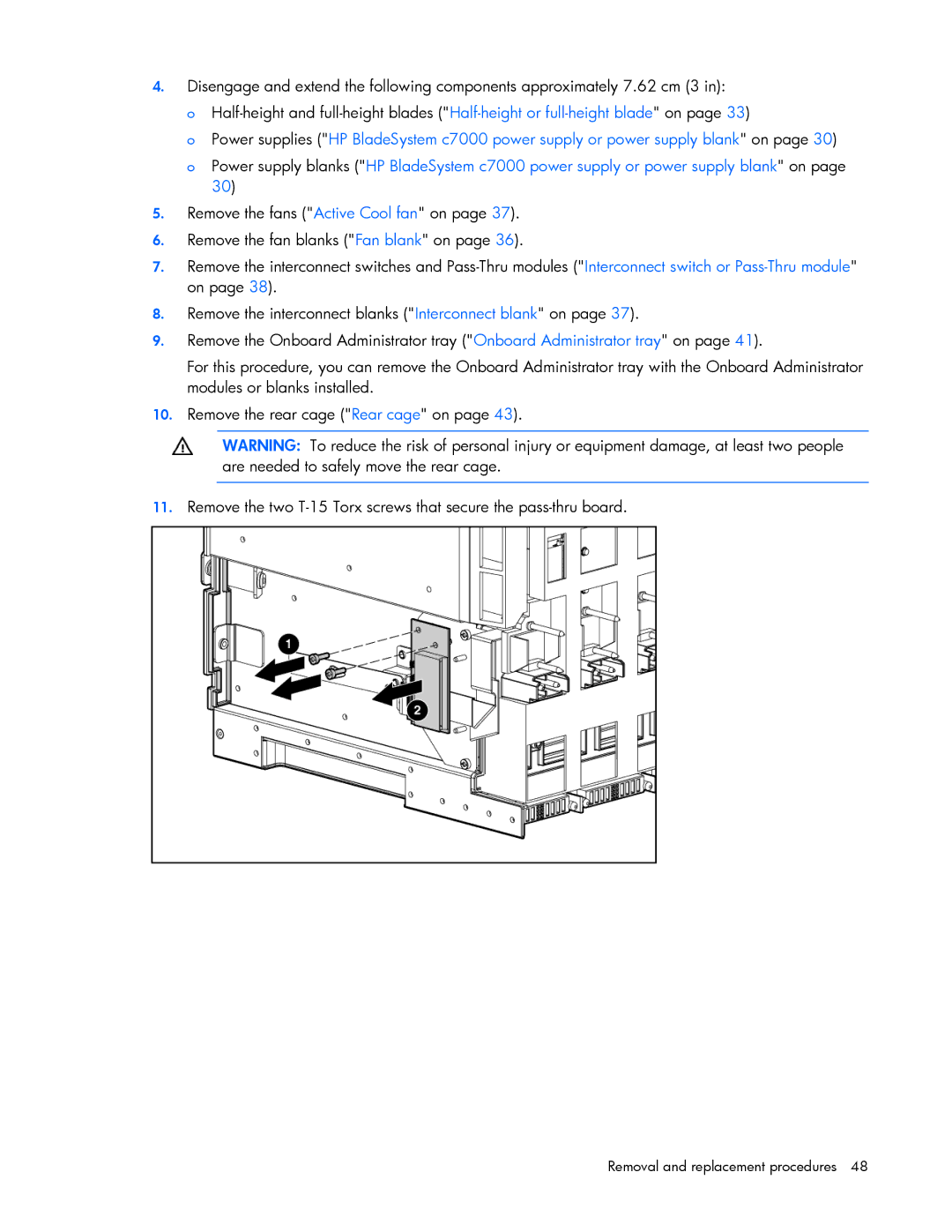
11.Remove the two