CAUTION: When removing the rear cage and midplane assembly, the connectors on the midplane assembly are susceptible to damage. Use caution to avoid damage to the pins and connectors.
10.Remove the rear cage ("Rear cage" on page 43).
11.Remove the Insight Display signal
WARNING: To reduce the risk of personal injury or equipment damage, at least two people are needed to safely move the rear cage.
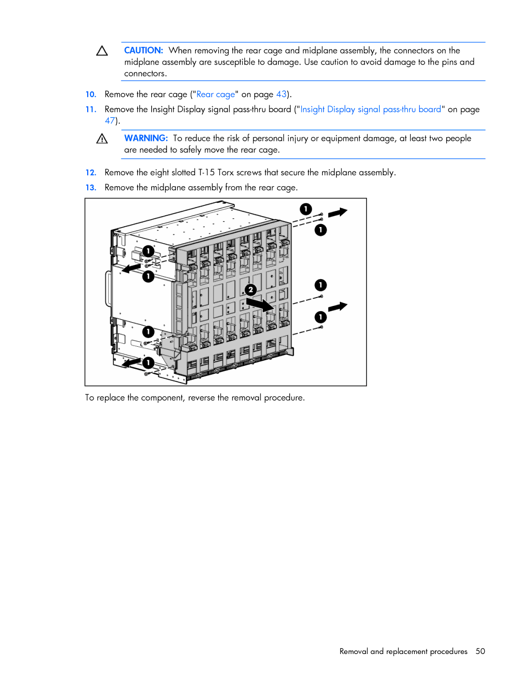
12.Remove the eight slotted
13.Remove the midplane assembly from the rear cage.
To replace the component, reverse the removal procedure.