45
Appendix A
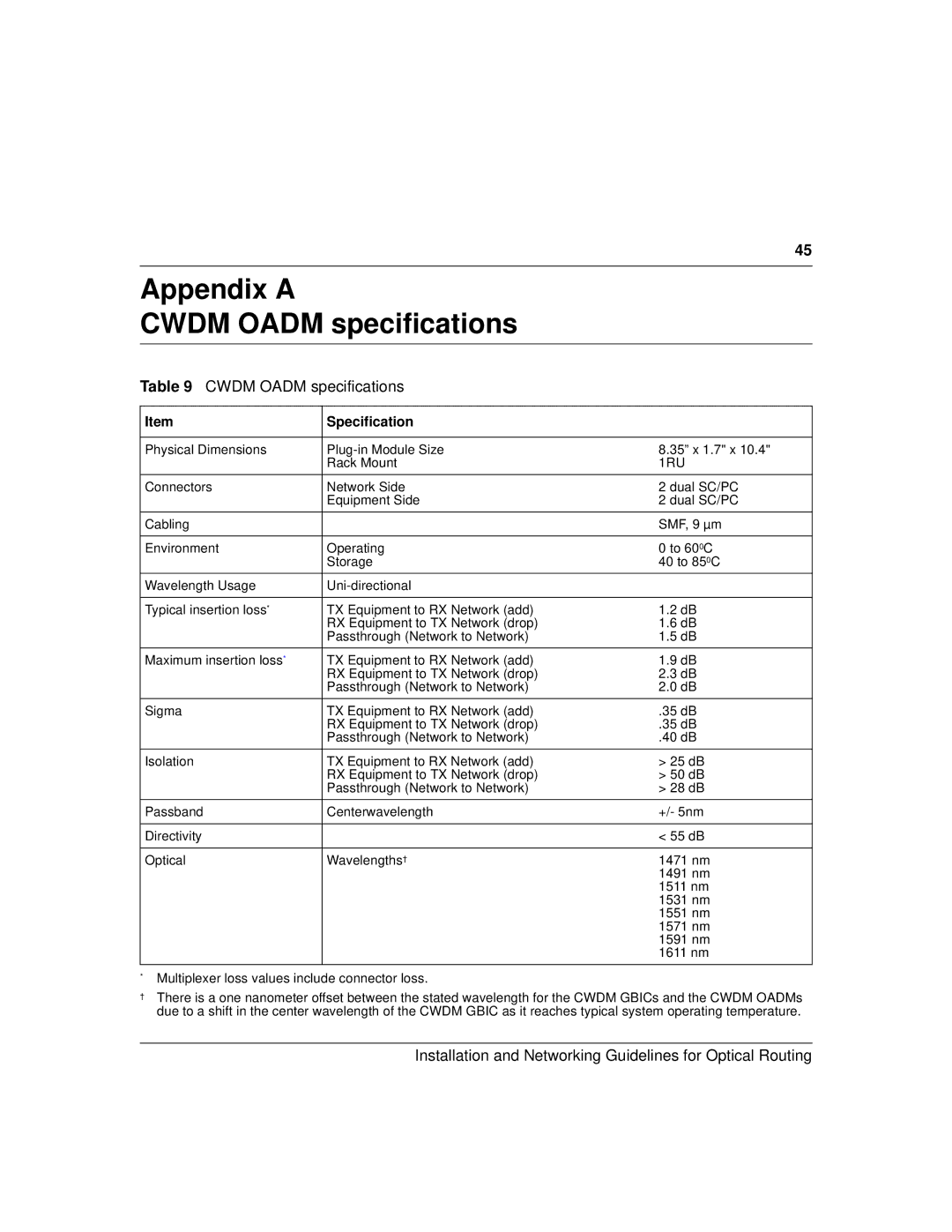
CWDM OADM specifications
Table 9 CWDM OADM specifications
Item | Specification |
|
|
|
|
Physical Dimensions | 8.35” x 1.7" x 10.4" | |
| Rack Mount | 1RU |
|
|
|
Connectors | Network Side | 2 dual SC/PC |
| Equipment Side | 2 dual SC/PC |
|
|
|
Cabling |
| SMF, 9 µm |
|
|
|
Environment | Operating | 0 to 600C |
| Storage | 40 to 850C |
|
|
|
Wavelength Usage |
| |
|
|
|
Typical insertion loss* | TX Equipment to RX Network (add) | 1.2 dB |
| RX Equipment to TX Network (drop) | 1.6 dB |
| Passthrough (Network to Network) | 1.5 dB |
|
|
|
Maximum insertion loss* | TX Equipment to RX Network (add) | 1.9 dB |
| RX Equipment to TX Network (drop) | 2.3 dB |
| Passthrough (Network to Network) | 2.0 dB |
|
|
|
Sigma | TX Equipment to RX Network (add) | .35 dB |
| RX Equipment to TX Network (drop) | .35 dB |
| Passthrough (Network to Network) | .40 dB |
|
|
|
Isolation | TX Equipment to RX Network (add) | > 25 dB |
| RX Equipment to TX Network (drop) | > 50 dB |
| Passthrough (Network to Network) | > 28 dB |
|
|
|
Passband | Centerwavelength | +/- 5nm |
|
|
|
Directivity |
| < 55 dB |
|
|
|
Optical | Wavelengths† | 1471 nm |
|
| 1491 nm |
|
| 1511 nm |
|
| 1531 nm |
|
| 1551 nm |
|
| 1571 nm |
|
| 1591 nm |
|
| 1611 nm |
|
|
|
*Multiplexer loss values include connector loss.
†There is a one nanometer offset between the stated wavelength for the CWDM GBICs and the CWDM OADMs due to a shift in the center wavelength of the CWDM GBIC as it reaches typical system operating temperature.