NXP Semiconductors | UM10301 |
| User Manual PCF85x3, PCA8565 and PCF2123, PCA2125 |
capacitances. The external components of the oscillator have to be chosen such that the actual value of CL matches the specified value of CL. If there is mismatch the crystal will not run exactly at its specified frequency resulting in the clock running slow or fast.
The crystal manufacturer can manufacture crystals for any load capacitance, but in practice some standard values are used. For use in
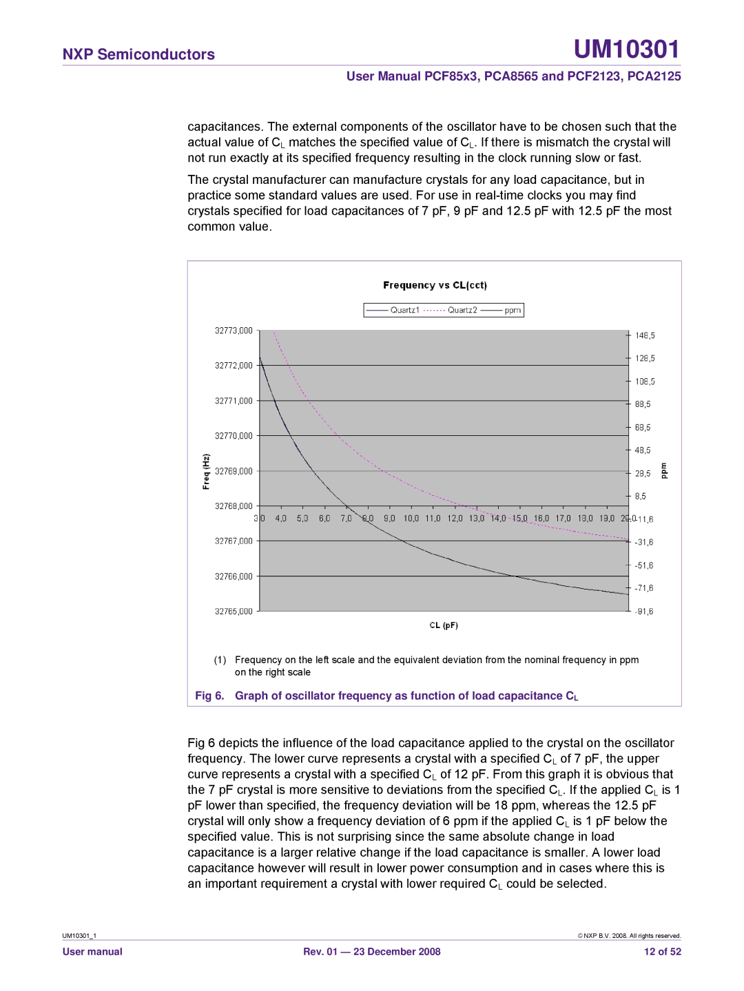
(1)Frequency on the left scale and the equivalent deviation from the nominal frequency in ppm on the right scale
Fig 6. Graph of oscillator frequency as function of load capacitance CL
Fig 6 depicts the influence of the load capacitance applied to the crystal on the oscillator frequency. The lower curve represents a crystal with a specified CL of 7 pF, the upper curve represents a crystal with a specified CL of 12 pF. From this graph it is obvious that the 7 pF crystal is more sensitive to deviations from the specified CL. If the applied CL is 1 pF lower than specified, the frequency deviation will be 18 ppm, whereas the 12.5 pF crystal will only show a frequency deviation of 6 ppm if the applied CL is 1 pF below the specified value. This is not surprising since the same absolute change in load capacitance is a larger relative change if the load capacitance is smaller. A lower load capacitance however will result in lower power consumption and in cases where this is an important requirement a crystal with lower required CL could be selected.
UM10301_1 |
| © NXP B.V. 2008. All rights reserved. |
User manual | Rev. 01 — 23 December 2008 | 12 of 52 |