NXP Semiconductors | UM10301 |
| User Manual PCF85x3, PCA8565 and PCF2123, PCA2125 |
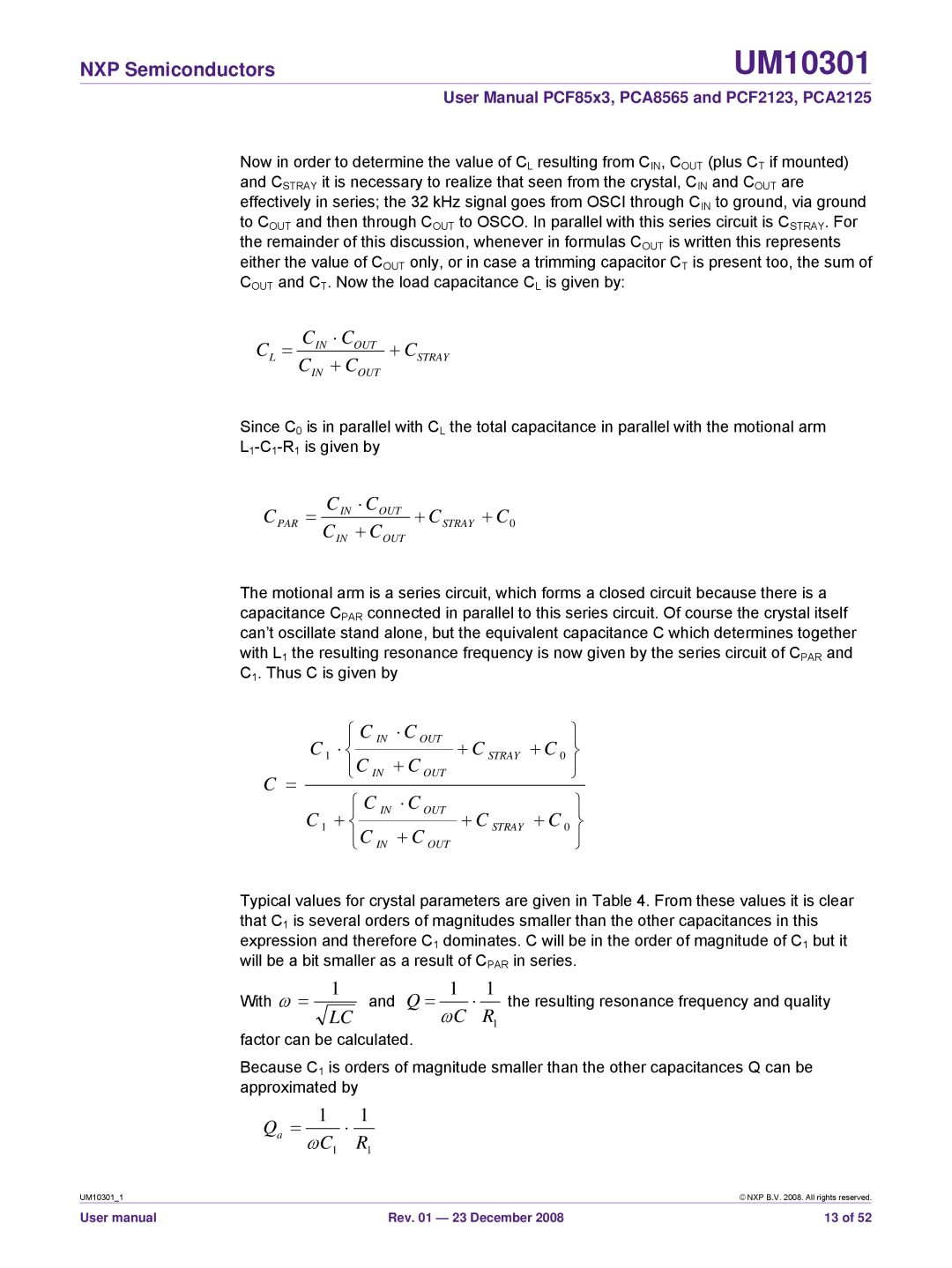
Now in order to determine the value of CL resulting from CIN, COUT (plus CT if mounted) and CSTRAY it is necessary to realize that seen from the crystal, CIN and COUT are effectively in series; the 32 kHz signal goes from OSCI through CIN to ground, via ground to COUT and then through COUT to OSCO. In parallel with this series circuit is CSTRAY. For the remainder of this discussion, whenever in formulas COUT is written this represents either the value of COUT only, or in case a trimming capacitor CT is present too, the sum of COUT and CT. Now the load capacitance CL is given by:
CL = | CIN ⋅ COUT | + CSTRAY |
| ||
| CIN + COUT | |
Since C0 is in parallel with CL the total capacitance in parallel with the motional arm
CPAR | = | CIN ⋅ COUT | + CSTRAY + C0 |
| |||
|
| CIN + COUT | |
The motional arm is a series circuit, which forms a closed circuit because there is a capacitance CPAR connected in parallel to this series circuit. Of course the crystal itself can’t oscillate stand alone, but the equivalent capacitance C which determines together with L1 the resulting resonance frequency is now given by the series circuit of CPAR and C1. Thus C is given by
|
|
|
| ⎧ | C | IN | ⋅ C | OUT |
|
|
|
|
|
|
| ⎫ | ||
| C |
| ⎪ |
|
|
| + C |
|
| + C |
|
| ⎪ | |||||
| 1 | ⋅ ⎨ |
|
|
|
|
|
|
| STRAY | 0 | ⎬ | ||||||
|
|
|
|
|
| |||||||||||||
|
|
| ⎪ |
|
| + C OUT |
|
|
| ⎪ | ||||||||
C = |
|
|
| ⎩C IN |
|
|
|
|
|
|
| ⎭ | ||||||
|
|
| ⎧ | C | IN | ⋅ C | OUT |
|
|
|
|
|
|
| ⎫ | |||
|
|
|
|
|
|
|
|
|
|
| ||||||||
| C |
|
| ⎪ |
|
|
|
| + C |
| + C |
| ⎪ | |||||
| 1 | + ⎨ |
|
|
|
|
|
| STRAY | 0 | ⎬ | |||||||
|
|
|
|
|
| |||||||||||||
|
| ⎪ |
|
| + C OUT |
|
|
|
|
| ⎪ | |||||||
|
|
|
| ⎩C IN |
|
|
|
|
|
|
| ⎭ | ||||||
Typical values for crystal parameters are given in Table 4. From these values it is clear that C1 is several orders of magnitudes smaller than the other capacitances in this expression and therefore C1 dominates. C will be in the order of magnitude of C1 but it will be a bit smaller as a result of CPAR in series.
With | ω = | 1 | and Q = | 1 | ⋅ | 1 | the resulting resonance frequency and quality | |||||
LC | ωC |
| ||||||||||
|
|
|
|
|
|
| R1 |
| ||||
factor can be calculated. |
|
|
|
|
| |||||||
Because C1 is orders of magnitude smaller than the other capacitances Q can be | ||||||||||||
approximated by |
|
|
|
|
| |||||||
Q |
| = |
| 1 | ⋅ | 1 |
|
|
|
|
|
|
a |
|
|
|
|
|
|
|
|
| |||
|
| ωC1 | R1 |
|
|
|
|
| ||||
|
|
|
|
|
|
|
| |||||
UM10301_1 |
|
|
|
|
|
|
|
|
|
|
| © NXP B.V. 2008. All rights reserved. |
User manual |
|
|
|
|
|
| Rev. 01 — 23 December 2008 | 13 of 52 | ||||