NXP Semiconductors | UM10301 |
| User Manual PCF85x3, PCA8565 and PCF2123, PCA2125 |
SDA
SCL
I2C interface
reset
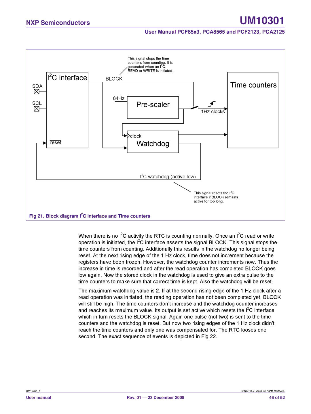
This signal stops the time counters from counting. It is generated when an I2C READ or WRITE is initiated.
BLOCK
64Hz
1Hz clocks
![]() clock
clock
Watchdog
I2C watchdog (active low)
Time counters
This signal resets the I2C interface if BLOCK remains active for too long.
Fig 21. Block diagram I2C interface and Time counters
When there is no I2C activity the RTC is counting normally. Once an I2C read or write operation is initiated, the I2C interface asserts the signal BLOCK. This signal stops the time counters from counting. Additionally this results in the watchdog no longer being reset. At the next rising edge of the 1 Hz clock, time does not increment because the registers have been frozen. However, the watchdog counter increments now. Thus the increase in time is recorded and after the read operation has completed BLOCK goes low again. Now the stored clock in the watchdog is used to give an extra pulse to the time counters to make sure that correct time is kept. Also the watchdog will be reset.
The maximum watchdog value is 2. If at the second rising edge of the 1 Hz clock after a read operation was initiated, the reading operation has not been completed yet, BLOCK will still be high. The time counters don’t increase and the watchdog counter increases and reaches its maximum value. Its output is set active which resets the I2C interface which in turn resets the BLOCK signal. Again one pulse (not two) is sent to the time counters and the watchdog is reset. But now two rising edges of the 1 Hz clock didn’t reach the time counters and only one was compensated for. The RTC looses one second. The exact sequence of events is depicted in Fig 22.
UM10301_1 |
| © NXP B.V. 2008. All rights reserved. |
User manual | Rev. 01 — 23 December 2008 | 46 of 52 |