SmartOnline 3-Phase UPS Systems
Table of Contents
Advanced Features
Introduction
Connection Warnings
Important Safety Instructions
Location Warnings
Battery Warnings
Wiring Warnings
Present and within standard operating parameters
Control Panel Features
To connected equipment. An audible alarm will also sound
Front and Rear Panel Features
Output Circuit Breaker Switch Q4 Controls AC output power
Rear View
Unpacking
Cabinet Installation
Preparation
Placement
Rear of the UPS system
Wiring
Wiring Preparation
UPS System Terminal Block Diagram
External Battery Cabinet Wiring Diagrams
External Battery Cabinets
Electrical and Cable Data
AC Input/Output Wiring Single UPS-SUS
Wiring
Output
Indb 12/28/2012 111726 AM
Online Normal Mode Single UPS-SUS
Battery Backup Mode Single UPS-SUS
Auto Bypass Mode Single UPS-SUS
Manual Bypass Mode Single UPS-SUS
Auto Bypass Mode Parallel UPS-MUS
Online Normal Mode Parallel UPS-MUS
Battery Backup Mode Parallel UPS-MUS
Manual Bypass Mode Parallel UPS-MUS
External Maintenance Bypass Mode Parallel UPS-MUS
Start-Up, Shutdown and Bypass
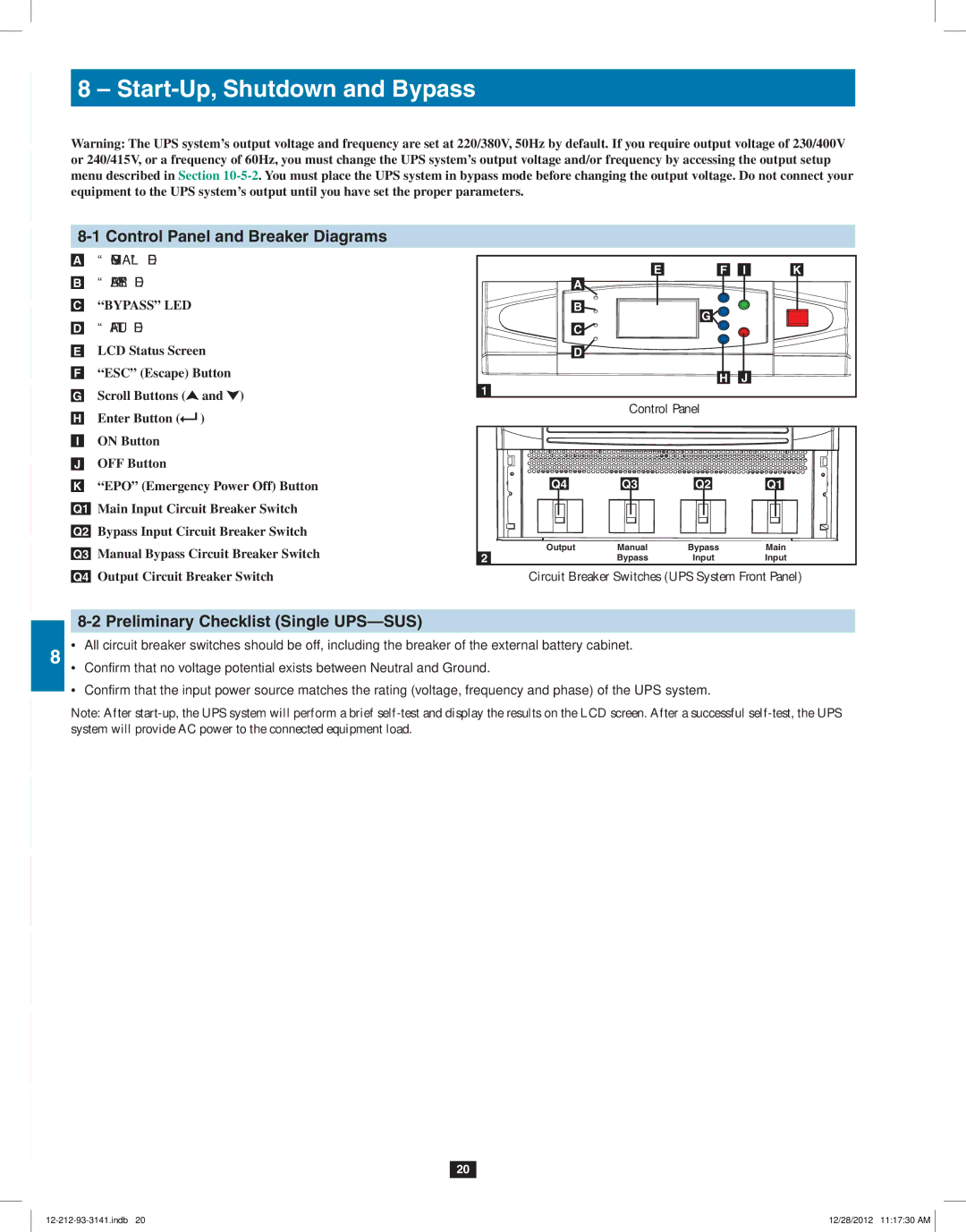
Control Panel and Breaker Diagrams
Preliminary Checklist Single UPS-SUS
Standard Start-Up Procedure Single UPS-SUS
Battery Start-Up Procedure Single UPS-SUS
Manual Bypass Procedure Single UPS-SUS
Desired values Prior to applying UPS inverter output to
Connected load See Section
Turn on the Manual Bypass circuit breaker LCD
Shutdown Procedure Single UPS-SUS
Preliminary Checklist Parallel UPS-MUS
Start-Up Procedure Parallel UPS-MUS
Shutdown Procedure Parallel UPS-MUS
Damage
Switch on the manual bypass input circuit breaker switch Q3
Bypass
Power Module Status and Replacement
Power Module Features and Status
Preliminary Replacement Checklist
Replacement Procedure
Display Hierarchy
Display and Configuration
Control Panel Diagram
Possible causes
Default Display
Status Display
UPS
Indb 12/28/2012 111801 AM
Main Menu
Indb 12/28/2012 111803 AM
UPS Setup
User
Bypass Setup
Press ESC to return to the UPS Setup menu Output Setup
Output Voltage
Press ESC to return to the UPS Setup menu Battery Setup
Redundancy
Battery Strings
Press ESC to return to the UPS Setup menu
Battery Next Replace Date
Charger Setup
Internal power modules has a charger current range
Parallel ID
Parallel Setup
Parallel Group
Buzzer
Control & Test Setup
Battery Auto Test
Force Boost Charge
Manual Battery Test
Clear Battery Test Result
Press ESC to return to the UPS Setup menu Local Setup
Date Format
LCD Contrast
Language
Administrator Password
User Password
Maintenance
Firmware Version
Use or to select the F/W version item, then press
Statistics
Event Log
Advanced
Snmpwebcard Slot Input Dry Contact Interface
Communications
Communications Interfaces
Remote Emergency Power Off EPO Circuit Diagram
Auxiliary Dry Contact Input Circuit Diagram
Optional Messages
Default Messages
Output Dry Contact Interface Detail
Output Dry Contact Circuit Diagram
11-10 RS-232 Serial Port Circuit Diagram
Parallel Configuration Port
Hardware Pin Assignment
UPS System Floor Loading Table
Specifications
UPS System Technical Specifications
Storage
Storage and Service
Service
Warranty
Limited Warranty
Manual del Propietario
Índice
English Français 117 Русский 175
Introducción
Características Avanzadas
Advertencias sobre la conexión
Instrucciones de seguridad importantes
Advertencias de ubicación
Advertencias sobre el cableado
Instrucciones de seguridad importantes Continuación
Advertencias sobre las baterías
Características del panel de control
Características del panel frontal y posterior
Vista Frontal
Características del panel frontal y posterior Continuación
Vista Posterior
Desembalaje
Instalación del Gabinete
Preparación
Instalación del Gabinete Continuación
Ubicación
Cableado
Preparación para el Cableado
Notas
Diagrama de Bloque de Terminales del Sistema UPS
Diagramas de Cableado del Gabinete de Baterías Externas
Datos Eléctricos y de los Cables
Gabinetes de Batería Externa
Cabledo del Gabinete de Baterías Externas
Cableado de Entrada/Salida de CA Un solo UPS-SUS
Advertencia Observe la polaridad apropiada conectando
Encadenamiento de la batería a N normal. Si no se respeta
Configuración en Paralelo Advertencias de MUS
Cableado Continuación
Modos de Operación
Modo En Línea Normal Un solo UPS-SUS
Modo de Respaldo por Batería Un solo UPS-SUS
Modo de Derivación Automática Un solo UPS-SUS
Modos de Operación Continuación
Modo En Línea Normal UPS en Paralelo-MUS
Modo de Respaldo por Batería UPS en Paralelo-MUS
Modo de Derivación Automático UPS en Paralelo-MUS
Modo de Derivación Manual UPS en Paralelo-MUS
Derivación Externa para Mantenimiento UPS en Paralelo-MUS
Lista de Comprobación Preliminar Un solo UPS-SUS
Diagramas de Tablero de Control y Breaker
Arranque, Apagado y Derivación
Arranque, Apagado y Derivación Continuación
Procedimiento de Arranque Estándar Un solo UPS-SUS
Procedimiento de Arranque por Batería Un solo UPS-SUS
Procedimiento de Derivación Manual Un solo UPS-SUS
Encienda el breaker de derivación manual El LCD mostrará
Procedimiento de Apagado Un solo UPS-SUS
Lista de Comprobación Preliminar UPS en Paralelo-MUS
Procedimiento de Arranque UPS en Paralelo-MUS
Consulte la Sección
Procedimiento de Apagado UPS en Paralelo-MUS
Pueden dañarse de manera irreversible
Derivación Manual
Indb 12/28/2012 111919 AM
Estado y Reemplazo del Módulo de Potencia
Características y Estado del Módulo de Potencia
Lista de Comprobación Preliminar de Reemplazo
Procedimiento de Reemplazo
Organización de la Pantalla
Pantalla y Configuración
Diagrama del Tablero de Control
Pantalla y Configuración Continuación
Pantalla Predeterminada
Pantalla de Estado
Causas Posibles
Pantalla de Estado Continuación
Pantalla y Configuración Continuación
10-4 Menú Principal
10-4 Menú Principal Continuación
No muestran datos reales
Configuración del UPS
Usuario
Configuración del UPS Continuación
Configuración de Derivación
Configuración de Derivación Continuación
Configuración de Salida Continuación
Voltaje de Salida
Redundancia
10 10-5-3 Configuración de Batería
Oprima ESC para regresar al menú
Configuración de Batería Continuación
Cadenas de Baterías
Próxima Fecha de Reemplazo de Batería
Configuración de Cargador
Oprima ESC para regresar al menú UPS Setup
Configuración en Paralelo
Grupo en Paralelo
Zumbador
Configuración de Control y Prueba
Autodiagnóstico de la Batería
Configuración de Control y Prueba Continuación
Prueba Manual de la Batería
Carga de Elevación de Fuerza
Borrar el Resultado de Prueba de la Batería
105
Contraste del LCD
Configuración Local Continuación
Formato de Fecha
Idioma
Contraseña del Administrador
Contraseña del Usuario
Estadísticas
Mantenimiento
Versión de Firmware
Avanzado
Mantenimiento Continuación
Registro de Eventos
Comunicaciones
Interfaces de Comunicaciones
Ranura Snmpwebcard
Interfaz de Entrada de Contacto Seco
Comunicaciones Continuación
Diagrama de Circuito de Apagado Remoto de Emergencia EPO
Diagrama de Circuito de Entrada Auxiliar de Contacto Seco
Mensajes Opcionales
Detalle de Interfaz de Salida de Contacto Seco
Mensajes Predeterminados
Diagrama de Circuito de Salida de Contacto Seco
Diagrama de Circuito de Puerto Serial RS-232
Puerto de Configuración en Paralelo
Hardware Asignación de Terminales
Mesa de Carga de Piso del Sistema UPS
Especificaciones
Especificaciones Técnicas del Sistema UPS
Servicio
Almacenamiento y servicio
Almacenamiento
Garantía
Garantía Limitada
Manuel de l’utilisateur
Table des matières
Câblage 127
Caractéristiques évoluées
Avertissements concernant les connexions
Avertissements concernant l’emplacement
Consignes de sécurité importantes
Avertissements concernant le câblage
Consignes de sécurité importantes suite
Avertissements concernant les batteries
Caractéristiques du panneau de commande
Caractéristiques du panneau avant et arrière
Vue de face
Caractéristiques du panneau avant et arrière suite
Vue arrière
Déballage
Installation de l’armoire
Préparation
Pas sur les côtés
Installation de l’armoire suite
Il faut être extrêmement prudent en déplaçant l’onduleur
Câblage
Préparation en vue du câblage
Câblage suite
Remarques
Armoires de batteries externes
Schémas de câblage de l’armoire de batteries externes suite
Système électrique et données sur le câble
Câblage de l’armoire de batteries externes
Câblage d’entrée/sortie CA onduleur simple-SUS
Câblage d’entrée/sortie CA configuration en parallèle-2x MUS
Câblage d’entrée/sortie CA configuration en parallèle-4x MUS
Mode en ligne normal onduleur simple-SUS
Mode batterie de secours onduleur simple-SUS
Mode dérivation automatique onduleur simple-SUS
Mode dérivation manuelle onduleur simple-SUS
Mode en ligne normal onduleur en parallèle-MUS
Mode batterie de secours onduleur en parallèle-MUS
Mode dérivation automatique onduleur en parallèle-MUS
Modes de fonctionnement suite
Mode dérivation manuelle onduleur en parallèle-MUS
Dérivation d’entretien externe onduleur en parallèle-MUS
Liste de vérifications préliminaire onduleur simple-SUS
Schémas du panneau de commande et des disjoncteurs
Démarrage, arrêt et dérivation
Démarrage, arrêt et dérivation suite
Procédure de démarrage standard onduleur simple-SUS
Procédure de démarrage sur batterie onduleur simple-SUS
Procédure de dérivation manuelle onduleur simple-SUS
Procédure de dérivation manuelle onduleur simple-SUS suite
Procédure d’arrêt onduleur simple-SUS
Liste de vérifications préliminaire onduleur simple-MUS
Procédure de démarrage onduleur en parallèle-MUS
Procédure d’arrêt onduleur en parallèle-MUS
Manuelle
144
Remplacement et état du module de puissance
Liste de vérifications préliminaire des remplacements
Procédure de remplacement
Caractéristiques et état du module de puissance
10-2 Hiérarchie de l’affichage
Affichage et configuration
10-1 Schéma du panneau de commande
Affichage et configuration suite
Affichage par défaut
Affichage de l’état
Causes possibles
Affichage de l’état suite
149
Menu principal
Menu principal suite
Configuration de l’onduleur
Administrateur personnel d’entretien qualifié Utilisateur
Configuration de l’onduleur suite
Configuration de la dérivation
Configuration de la dérivation suite
Configuration de la sortie suite
Tension de sortie
Redondance
Configuration de la batterie suite
Chaînes de batteries
Date du prochain remplacement de la batterie
Configuration du chargeur
Parallel ID identification en parallèle
Configuration en parallèle
Groupe parallèle
Vibreur sonore
Configuration des contrôles et des tests
Auto-test de la batterie
Configuration des contrôles et des tests suite
Test manuel de la batterie
Charge forcée
Effacer le résultat du test de la batterie
163
Contraste ACL
Configuration locale suite
Format de la date
Langue
Mot de passe de l’administrateur
Mot de passe de l’utilisateur
Statistiques
Entretien
Version du micrologiciel
Évolué
Entretien suite
Journal des événements
Interfaces de communication
Fente Snmpwebcard Interface des contacts secs d’entrée
Communications suite
Messages optionnels
11-8 Détail de l’interface des contacts secs de sortie
Messages par défaut
Port de configuration en parallèle
11-9 Schéma du circuit des contacts secs de sortie
11-10 Schéma du circuit du port de série RS-232
Quincaillerie Affectation des broches
Spécifications
12-1 Spécifications techniques de l’onduleur
Entreposage et entretien
Entreposage
Garantie
Garantie limitée
Руководство пользователя
Содержание
Монтаж проводки 185
Введение
Расширенные возможности
Важные указания по технике безопасности
Правилам электромонтажа
Важные указания по технике безопасности Продолжение
Предупреждения относительно батарей
Свойства панели управления
Диагностическая информация отображается на ЖК-экране
Свойства передней и задней панелей
Вид спереди
Параллельную схему
Свойства передней и задней панелей Продолжение
Электропитания
Распаковка
Установка шкафа
Подготовка
Установка шкафа Продолжение
Размещение
Перемещения ИБП по неустойчивой поверхности существует
Боков
Подготовка к монтажу
Монтаж проводки
Предупреждения относительно монтажа
Монтаж проводки Продолжение
Примечания
Электрические схемы внешних батарейных шкафов Продолжение
Электрические параметры и характеристики кабелей
Монтаж проводки внешних батарейных шкафов
Максимальное отклонение должно быть 10%
Ущерба
190
Рабочие режимы
Режим онлайн нормальный одиночный ИБП SUS
Режим питания от батарей одиночный ИБП SUS
Ручной режим работы по обходной цепи одиночный ИБП SUS
Рабочие режимы Продолжение
Режим онлайн нормальный параллельно включенные ИБП MUS
Внешний ремонтный байпас параллельно включенные ИБП MUS
Выходной автоматический выключатель
Начальный запуск, отключение и байпас
Автоматический выключатель ручного байпаса
Начальный запуск, отключение и байпас Продолжение
Типовой порядок начального запуска одиночный ИБП SUS
Порядок начального запуска батарей одиночный ИБП SUS
197
Порядок отключения одиночный ИБП SUS
Порядок начального запуска параллельно включенные ИБП MUS
Порядок отключения параллельно включенные ИБП MUS
Установленные лимиты
Q4Q2
Статус и замена силовых модулей
Свойства и статус силового модуля
Предварительный перечень контрольных операций перед заменой
Порядок замены
10-2 Иерархия отображения
10 Отображение данных и конфигурация
10-1 Схема расположения элементов панели управления
10 Отображение данных и конфигурация Продолжение
10-3 Отображение по умолчанию
10-3-1 Отображение статуса
Возможные причины
10-3-1 Отображение статуса Продолжение
Запуск ИБП производится за счет питания от батарей
207
10-4 Главное меню
ИБП функционирует в экономичном режиме, а электропитание
10-4 Главное меню Продолжение
10-5 Начальная установка параметров ИБП
Пользователь
10-5 Начальная установка параметров ИБП Продолжение
10-5-1 Начальная установка параметров обходной цепи
212
10-5-2 Начальная установка выходных параметров Продолжение
Выходное напряжение
Схеме
10-5-3 Начальная установка параметров батареи Продолжение
Батарейные секции
Нажмите кнопку ESC для возврата в меню UPS Setup
Дата следующей замены батареи
10-5-4 Начальная установка параметров зарядного устройства
Ид. параллельного включения
11 Нажмите кнопку ESC для возврата в меню UPS Setup
Параллельная группа
Автоматическое тестирование батареи
Устройство звуковой сигнализации
Удалить результат тестирования батареи
Ручное тестирование батареи
Форсированная подзарядка
221
10-5-7 Начальная установка локальных параметров Продолжение
Формат данных
Язык
Пароль администратора
Пароль пользователя
Статистика
10-6 Техническое обслуживание
Версия прошивки
Дополнительно
10-6 Техническое обслуживание Продолжение
Журнал регистрации событий
11 Система связи
11-1 Интерфейсы связи
11 Система связи Продолжение
Сообщения, передаваемые по умолчанию
Опциональные сообщения
Контакт Сообщение Описание
Сообщение Описание
Аппаратное обеспечение Разводка контактов
11-10 Принципиальная схема последовательного порта RS-232
11-11 Порт параллельного соединения
12-2 Таблица допустимых нагрузок на пол, создаваемых ИБП
12 Технические характеристики
12-1 Технические характеристики ИБП
Техническое обслуживание
13 Хранение и обслуживание
Хранение
14 Гарантийные обязательства
Ограниченная гарантия