NXP Semiconductors | UM10301 |
| User Manual PCF85x3, PCA8565 and PCF2123, PCA2125 |
The timer counts down from a
If a new value of n is written before the end of the current timer period, then this value will take immediate effect. It is not recommended (especially when using the faster time source clocks) to change n without first disabling the counter. The counter is disabled by setting Timer Enable TE = 0. The update of n is asynchronous to the timer clock, therefore changing it without setting TE = 0 may result in a corrupted value loaded into the countdown counter which results in an undetermined countdown period for the first period. However, the probability of this happening depends on the selected timer source clock. If the timer clock is not first stopped then there is a possibility that the timer clock and the interface clock which is loading the count down timer could arrive at the same time. This may corrupt the count down value. With a
Also in the case where the timer clock and the interface clock arrive at the same time which may corrupt the first count down value, the countdown value n will however be correctly stored and correctly loaded on subsequent timer periods.
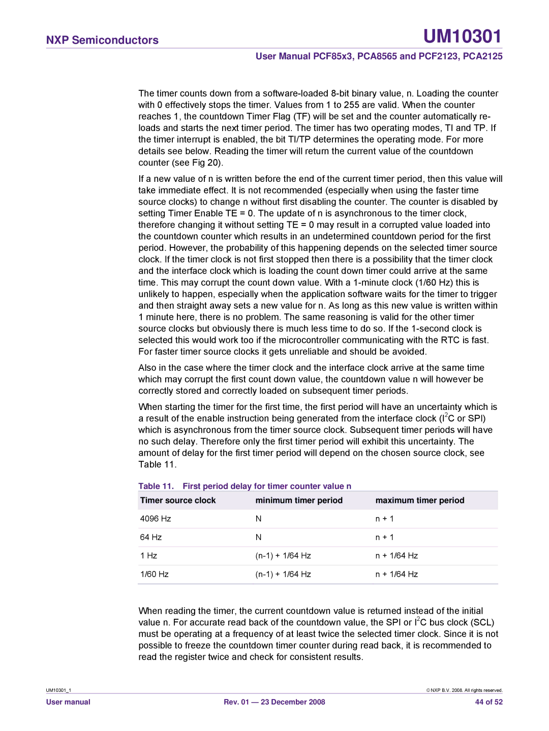
When starting the timer for the first time, the first period will have an uncertainty which is a result of the enable instruction being generated from the interface clock (I2C or SPI) which is asynchronous from the timer source clock. Subsequent timer periods will have no such delay. Therefore only the first timer period will exhibit this uncertainty. The amount of delay for the first timer period will depend on the chosen source clock, see Table 11.
Table 11. First period delay for timer counter value n
Timer source clock | minimum timer period | maximum timer period |
|
|
|
4096 Hz | N | n + 1 |
|
|
|
64 Hz | N | n + 1 |
|
|
|
1 Hz | n + 1/64 Hz | |
|
|
|
1/60 Hz | n + 1/64 Hz | |
|
|
|
When reading the timer, the current countdown value is returned instead of the initial value n. For accurate read back of the countdown value, the SPI or I2C bus clock (SCL) must be operating at a frequency of at least twice the selected timer clock. Since it is not possible to freeze the countdown timer counter during read back, it is recommended to read the register twice and check for consistent results.
UM10301_1 |
| © NXP B.V. 2008. All rights reserved. |
User manual | Rev. 01 — 23 December 2008 | 44 of 52 |