NXP Semiconductors | UM10301 |
| User Manual PCF85x3, PCA8565 and PCF2123, PCA2125 |
12. Initialization and setting of alarm and timer
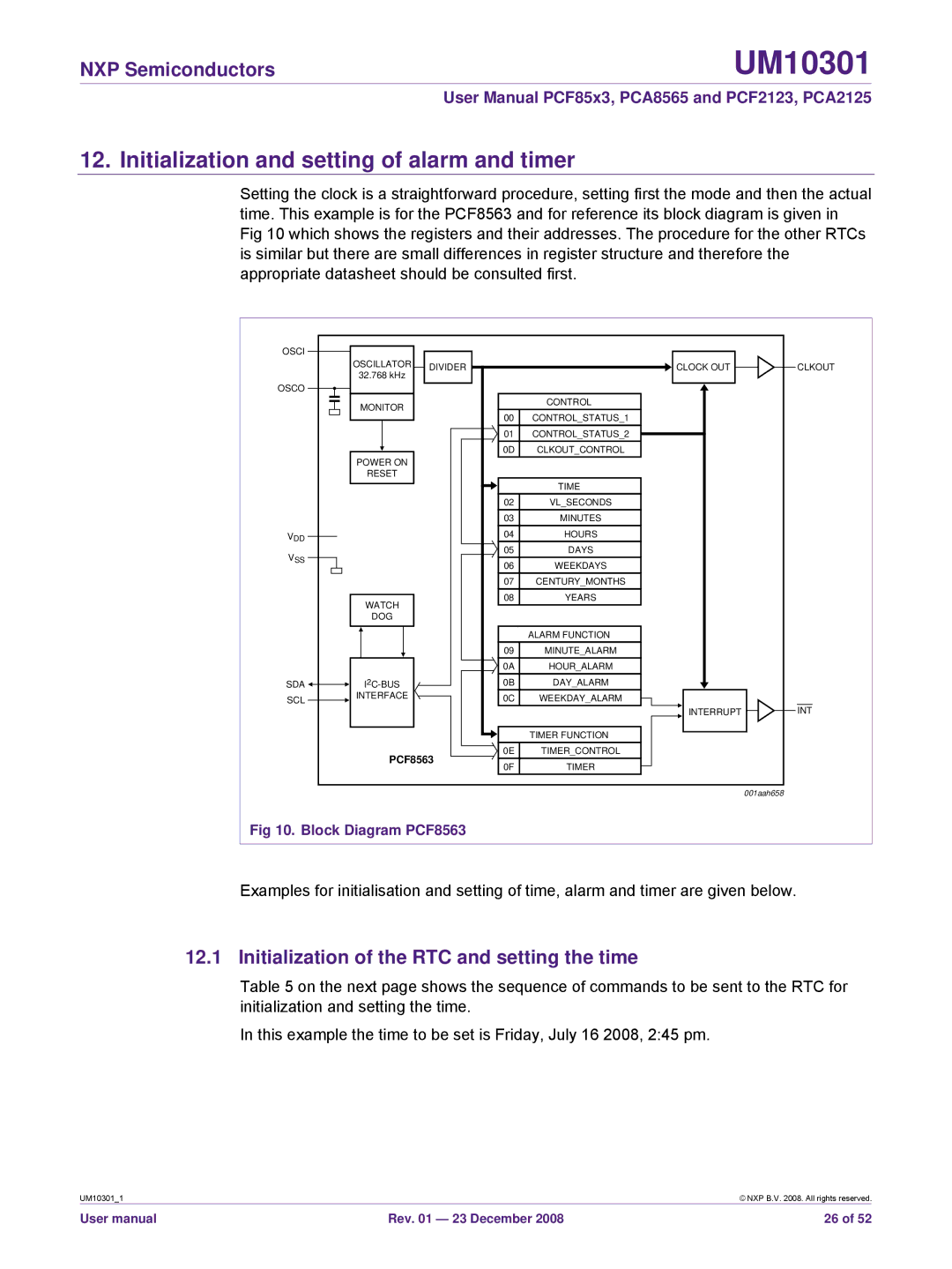
Setting the clock is a straightforward procedure, setting first the mode and then the actual time. This example is for the PCF8563 and for reference its block diagram is given in Fig 10 which shows the registers and their addresses. The procedure for the other RTCs is similar but there are small differences in register structure and therefore the appropriate datasheet should be consulted first.
OSCI |
|
|
|
|
| OSCILLATOR | DIVIDER |
| CLOCK OUT |
| 32.768 kHz |
| ||
|
|
|
| |
OSCO |
|
|
|
|
| MONITOR |
|
| CONTROL |
|
| 00 | CONTROL_STATUS_1 | |
|
|
| ||
|
|
| 01 | CONTROL_STATUS_2 |
|
|
| 0D | CLKOUT_CONTROL |
| POWER ON |
|
|
|
| RESET |
|
|
|
|
|
|
| TIME |
|
|
| 02 | VL_SECONDS |
|
|
| 03 | MINUTES |
VDD |
|
| 04 | HOURS |
VSS |
|
| 05 | DAYS |
|
| 06 | WEEKDAYS | |
|
|
| 07 | CENTURY_MONTHS |
| WATCH |
| 08 | YEARS |
|
|
|
| |
| DOG |
|
|
|
|
|
|
| ALARM FUNCTION |
|
|
| 09 | MINUTE_ALARM |
|
|
| 0A | HOUR_ALARM |
SDA |
| 0B | DAY_ALARM | |
SCL | INTERFACE |
| 0C | WEEKDAY_ALARM |
|
|
|
| INTERRUPT |
|
|
|
| TIMER FUNCTION |
| PCF8563 | 0E | TIMER_CONTROL | |
| 0F | TIMER | ||
|
|
| ||
|
|
|
| 001aah658 |
CLKOUT
INT
Fig 10. Block Diagram PCF8563
Examples for initialisation and setting of time, alarm and timer are given below.
12.1 Initialization of the RTC and setting the time
Table 5 on the next page shows the sequence of commands to be sent to the RTC for initialization and setting the time.
In this example the time to be set is Friday, July 16 2008, 2:45 pm.
UM10301_1 |
| © NXP B.V. 2008. All rights reserved. |
User manual | Rev. 01 — 23 December 2008 | 26 of 52 |