NXP Semiconductors | UM10301 |
| User Manual PCF85x3, PCA8565 and PCF2123, PCA2125 |
In BCD every digit of the decimal system is represented by a
This is not the same as binary representation. It is clear that BCD is not the most efficient way of coding since every
Each
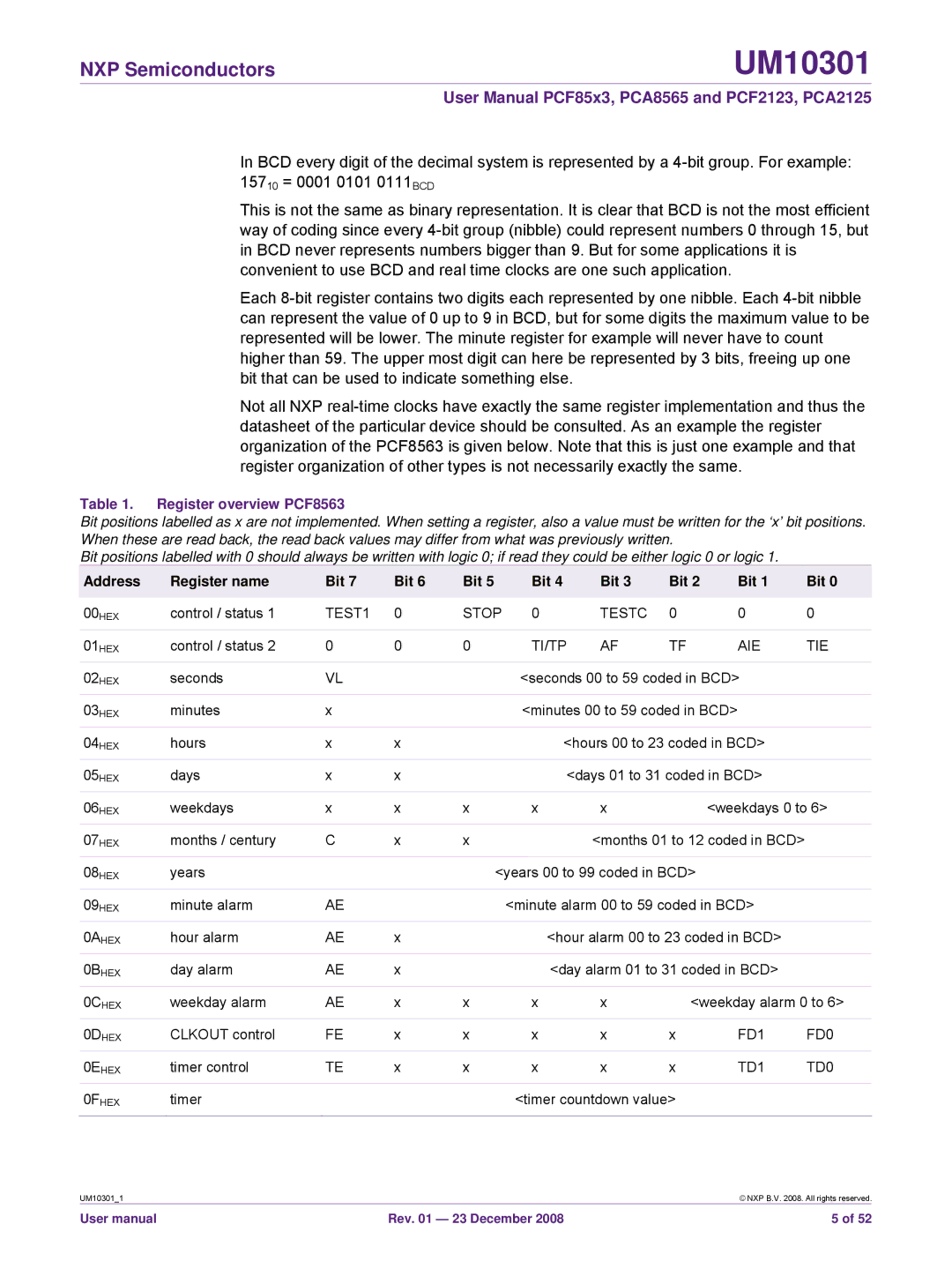
Not all NXP
Table 1. Register overview PCF8563
Bit positions labelled as x are not implemented. When setting a register, also a value must be written for the ‘x’ bit positions. When these are read back, the read back values may differ from what was previously written.
Bit positions labelled with 0 should always be written with logic 0; if read they could be either logic 0 or logic 1.
Address | Register name | Bit 7 | Bit 6 | Bit 5 |
| Bit 4 | Bit 3 | Bit 2 | Bit 1 | Bit 0 |
|
|
|
|
|
|
|
|
|
|
|
00HEX | control / status 1 | TEST1 | 0 | STOP | 0 | TESTC | 0 | 0 | 0 | |
|
|
|
|
|
|
|
|
|
|
|
01HEX | control / status 2 | 0 | 0 | 0 |
| TI/TP | AF | TF | AIE | TIE |
|
|
|
|
|
|
|
| |||
02HEX | seconds | VL |
|
| <seconds 00 to 59 coded in BCD> |
| ||||
|
|
|
|
|
|
|
| |||
03HEX | minutes | x |
|
| <minutes 00 to 59 coded in BCD> |
| ||||
|
|
|
|
|
|
|
| |||
04HEX | hours | x | x |
|
| <hours 00 to 23 coded in BCD> |
| |||
|
|
|
|
|
|
|
| |||
05HEX | days | x | x |
|
| <days 01 to 31 coded in BCD> |
| |||
|
|
|
|
|
|
|
|
|
| |
06HEX | weekdays | x | x | x |
| x | x |
| <weekdays 0 to 6> | |
|
|
|
|
|
|
|
|
| ||
07HEX | months / century | C | x | x |
|
| <months 01 to 12 coded in BCD> |
| ||
|
|
|
|
|
|
|
| |||
08HEX | years |
|
| <years 00 to 99 coded in BCD> |
|
| ||||
|
|
|
|
|
|
| ||||
09HEX | minute alarm | AE |
|
| <minute alarm 00 to 59 coded in BCD> |
| ||||
|
|
|
|
|
|
|
| |||
0AHEX | hour alarm | AE | x |
|
| <hour alarm 00 to 23 coded in BCD> |
| |||
|
|
|
|
|
|
|
| |||
0BHEX | day alarm | AE | x |
|
| <day alarm 01 to 31 coded in BCD> |
| |||
|
|
|
|
|
|
|
|
| ||
0CHEX | weekday alarm | AE | x | x |
| x | x | <weekday alarm 0 to 6> | ||
|
|
|
|
|
|
|
|
|
|
|
0DHEX | CLKOUT control | FE | x | x |
| x | x | x | FD1 | FD0 |
|
|
|
|
|
|
|
|
|
|
|
0EHEX | timer control | TE | x | x |
| x | x | x | TD1 | TD0 |
|
|
|
|
|
|
|
| |||
0FHEX | timer |
|
|
| <timer countdown value> |
|
| |||
|
|
|
|
|
|
|
|
|
|
|
UM10301_1 |
| © NXP B.V. 2008. All rights reserved. |
User manual | Rev. 01 — 23 December 2008 | 5 of 52 |