FLR Flow Transmitter Installation & Programming Instructions
Programming Flow Chart
The programming flow chart on pages 10 and 11 will aid understanding of the menu structure of the FLR Flow Transmitter. It will also help with understanding the available configuration selections.
Programming Descriptions
Display Mode
The meter can display RATE (flow rate) or TOTAL (total accumulated flow) or alternate between BOTH rate and total. Its displayed name is DISPLAY and is viewed or changed using the List Item Selection Procedure found on page 8.
Rate Units of Measure
The meter allows the selection of many common rate units. Its displayed name is RATE UNT and is viewed or changed using the List Item Selection Procedure found on page 8.
Rate (Time) Interval
The meter allows selection of several intervals based on time. Its displayed name is RATE INT and is viewed or changed using the List Item Selection Procedure found on page 8.
Total Units of Measure
If the total flow is being displayed, the units for the total must first be chosen. The monitor allows the choice of many common totalization units. Its displayed name is TOTL UNT and is viewed or changed using the List Item Selection Procedure found on page 8.
Total Display Multiplier
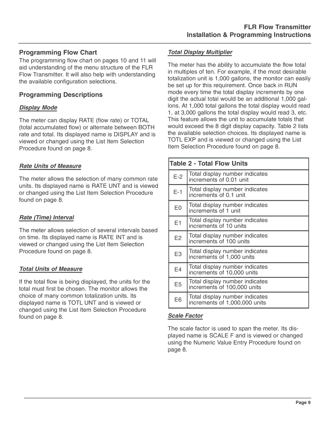
The meter has the ability to accumulate the flow total in multiples of ten. For example, if the most desirable totalization unit is 1,000 gallons, the monitor can easily be set up for this requirement. Once back in RUN mode every time the total display increments by one digit the actual total would be an additional 1,000 gal- lons. At 1,000 total gallons the total display would read 1, at 3,000 gallons the total display would read 3, etc. This feature allows the unit to accumulate totals that would exceed the 8 digit display capacity. Table 2 lists the available selection choices. Its displayed name is TOTL EXP and is viewed or changed using the List Item Selection Procedure found on page 8.
Table 2 - Total Flow Units
Total display number indicates | ||
increments of 0.01 unit | ||
| ||
|
| |
Total display number indicates | ||
increments of 0.1 unit | ||
| ||
|
| |
E0 | Total display number indicates | |
increments of 1 unit | ||
| ||
|
| |
E1 | Total display number indicates | |
increments of 10 units | ||
| ||
|
| |
E2 | Total display number indicates | |
increments of 100 units | ||
| ||
|
| |
E3 | Total display number indicates | |
increments of 1,000 units | ||
| ||
|
| |
E4 | Total display number indicates | |
increments of 10,000 units | ||
| ||
|
| |
E5 | Total display number indicates | |
increments of 100,000 units | ||
| ||
|
| |
E6 | Total display number indicates | |
increments of 1,000,000 units | ||
| ||
|
|
Scale Factor
The scale factor is used to span the meter. Its dis- played name is SCALE F and is viewed or changed using the Numeric Value Entry Procedure found on page 8.
Page 9