Manuals
/
Omega Engineering
/
Marine Equipment
/
Marine Sanitation System
Omega Engineering
FLR8000 series FLR Flow Transmitter Installation & Programming Instructions
Models:
FLR9000 series
FLR6000 series
FLR5000 series
FLR7000 series
FLR8000 series
1
12
28
28
Download
28 pages
15.99 Kb
9
10
11
12
13
14
15
16
Troubleshooting
Specification
Install
Warranty
Maintenance
List Item Selection Procedure
Normal Operation RUN Mode
Page 12
Image 12
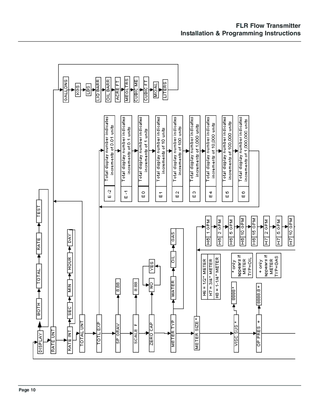
FLR Flow Transmitter Installation & Programming Instructions
Page 10
Page 11
Page 13
Page 12
Image 12
Page 11
Page 13
Contents
User’s Guide
Servicing North America
Introduction
FLR Flow Transmitter
II. Specifications
III. Installation
Electrical Connections
Terminology
Installing the Transmitter
Normal Operation RUN Mode
IV. Operation
Operating the Meter
Programming Operation Program Mode
Cover Removal/Reinstallation
List Item Selection Procedure
Programming Descriptions
Total Flow Units
FLR Flow Transmitter Installation & Programming Instructions
FLR Flow Transmitter Installation & Programming Instructions
Meter Size Types
Zero Capture
Output Mode
Maintenance
Cartridge Cleaning on page 5 and on
VI. Troubleshooting
VII. Appendix
Correction Factors
Fluid Selection
Flow vs. Pressure Drop
Water
Petroleum Fluids
Phosphate Ester
I. Oil
Air / Compressed Gases
FLR Flow Transmitter Installation & Programming Instructions
FLR Flow Transmitter Installation & Programming Instructions
WARRANTY/ Disclaimer
Shop online at omega.com
Top
Page
Image
Contents