FLR Flow Transmitter
Installation & Programming Instructions
Schematics
The transmitter can be wired in various configurations to allow interface with many different types of data col- lection and control instrumentation.
Schematics 1 & 2 represent typical wiring for a target powered by either AC power or DC supply.
Schematics 3 & 4 will be utilized when the flow trans-
mitter is operated with
excitation available.
Schematic 1:
Schematic 2:
Schematic 3:
Schematic 4:
®
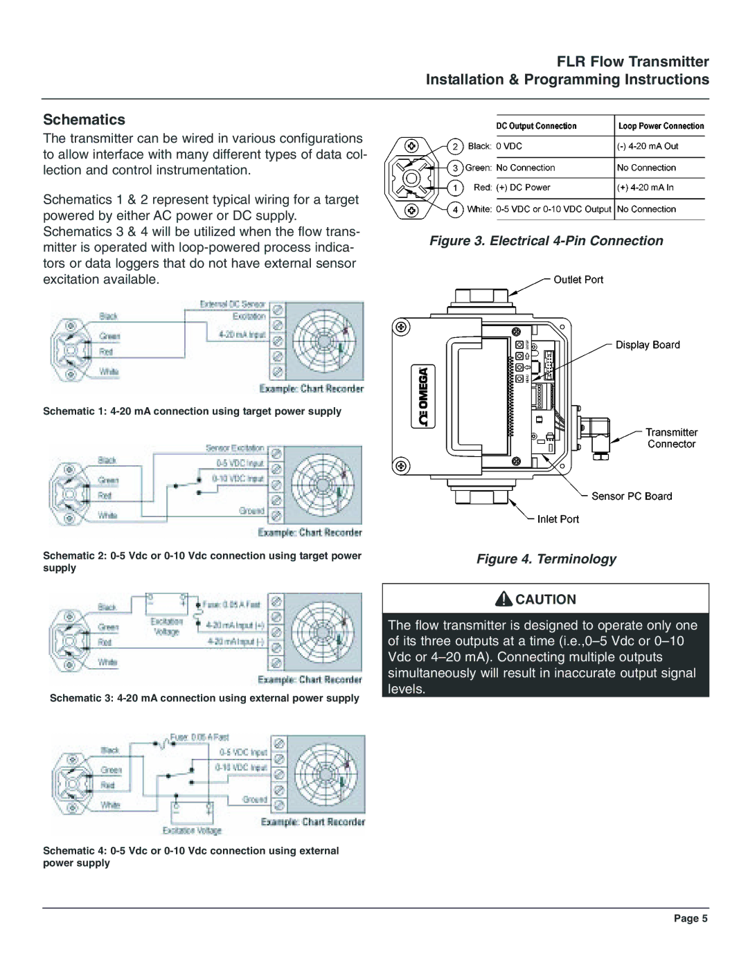
Figure 4. Terminology
![]() CAUTION
CAUTION
The flow transmitter is designed to operate only one of its three outputs at a time
Page 5