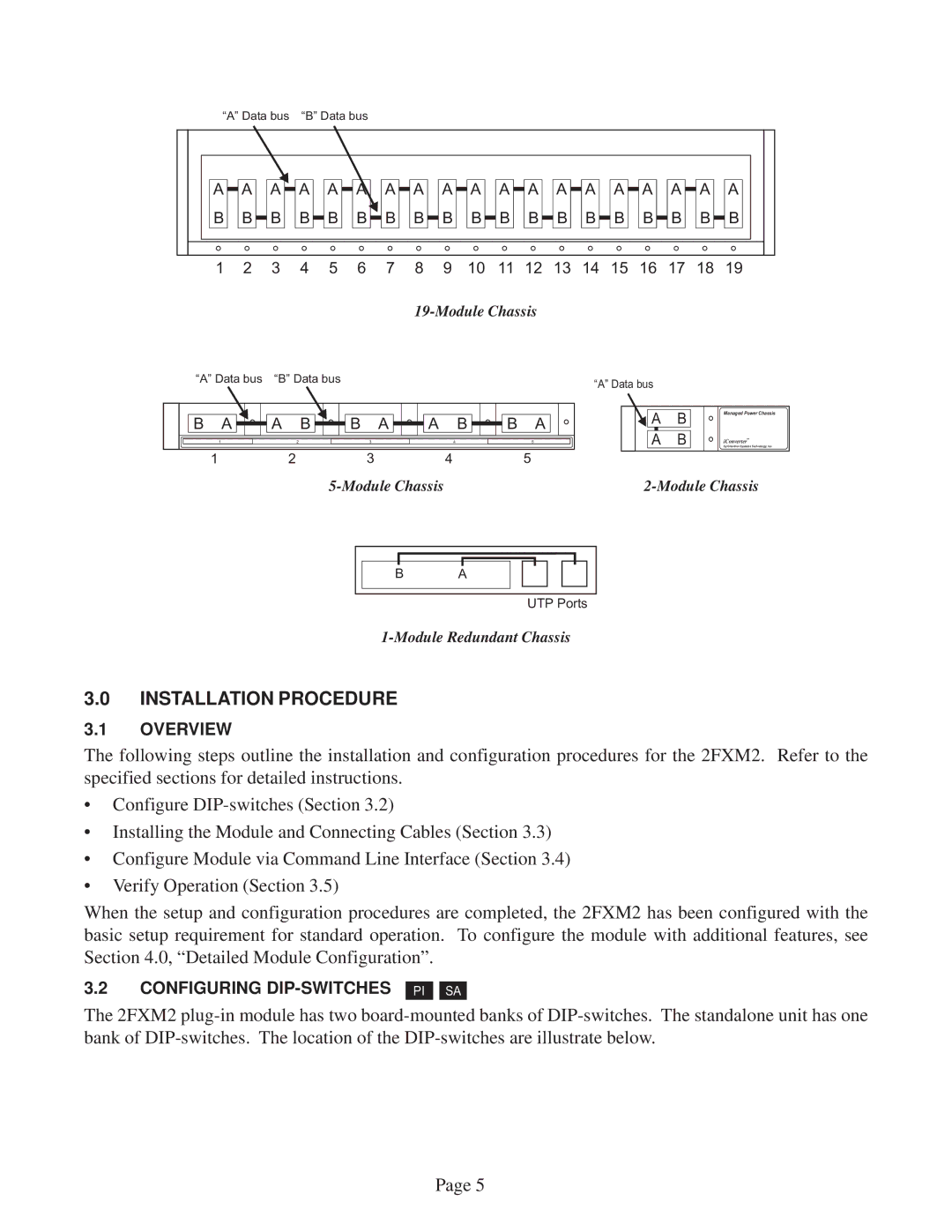
“A” Data bus “B” Data bus
A A | A | A | A A | A | A | A | A | A | A | A | A | A | A | A | A | A | ||
B | B B B B B B B B B | B | B | B | B | B | B | B | B | B | ||||||||
1 | 2 | 3 | 4 | 5 | 6 | 7 | 8 | 9 | 10 11 12 13 14 15 16 17 18 19 | |||||||||
“A” Data bus “B” Data bus
B | A | A | B | B | A | A | B | B | A |
“A” Data bus
A B
Managed Power Chassis
1 | 2 | 3 | 4 | 5 |
1 | 2 | 3 | 4 | 5 |
A | B | iConverter™ |
by Omnitron Systems Technology, Inc. |
B A
UTP Ports
3.0INSTALLATION PROCEDURE
3.1OVERVIEW
The following steps outline the installation and configuration procedures for the 2FXM2. Refer to the specified sections for detailed instructions.
•Configure
•Installing the Module and Connecting Cables (Section 3.3)
•Configure Module via Command Line Interface (Section 3.4)
•Verify Operation (Section 3.5)
When the setup and configuration procedures are completed, the 2FXM2 has been configured with the basic setup requirement for standard operation. To configure the module with additional features, see Section 4.0, “Detailed Module Configuration”.
3.2CONFIGURING
PI
SA
The 2FXM2
Page 5