3.0INSTALLATION PROCEDURE
3.1OVERVIEW
The following steps outline the installation and configuration procedures for the NMM. Refer to the specified sections for detailed instructions.
•Configuring Switches (Section 3.2)
•Installing the Module and Connecting the UTP Cable (Section 3.3)
•Configure the Module via Command Line Interface (Section 3.4)
•Verify Operation (Section 3.5)
When the setup and configuration procedures are completed, the NMM has been configured for operation.
3.2CONFIGURING SWITCHES
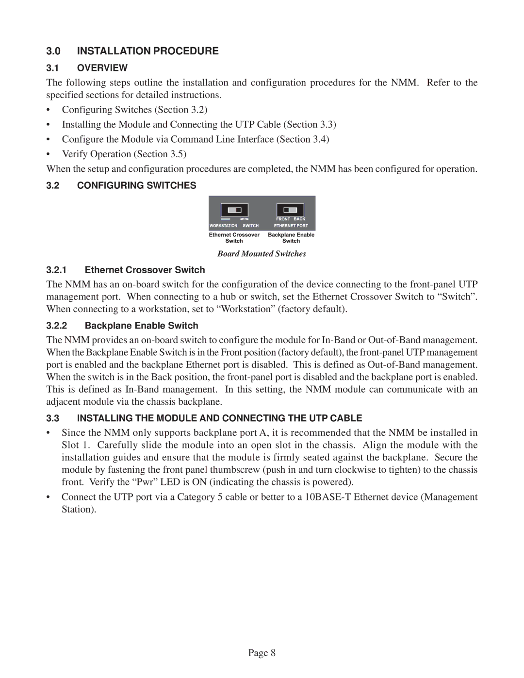
Board Mounted Switches
3.2.1Ethernet Crossover Switch
The NMM has an
3.2.2Backplane Enable Switch
The NMM provides an
3.3INSTALLING THE MODULE AND CONNECTING THE UTP CABLE
•Since the NMM only supports backplane port A, it is recommended that the NMM be installed in Slot 1. Carefully slide the module into an open slot in the chassis. Align the module with the installation guides and ensure that the module is firmly seated against the backplane. Secure the module by fastening the front panel thumbscrew (push in and turn clockwise to tighten) to the chassis front. Verify the “Pwr” LED is ON (indicating the chassis is powered).
•Connect the UTP port via a Category 5 cable or better to a
Page 8
