Safety Precautions
Refer to the “Precautions for All Switches” on page
Safety Door Switches
D4BL
!CAUTION
Do not insert the Operation Key when the door is open. The machine may operate, possibly resulting in injury. Before using the machine, be sure to remove the shock- absorbing damper, which is provided before shipping.
■Precautions for Safe Use
•Do not use the Switch submersed in oil or water or in locations continuously subject to splashes of oil or water. Doing so may result in oil or water entering the Switch. (The IP67 degree of protection of the Switch specifies the amount of water penetration after the Switch is submerged in water for a certain period of time.)
•Although the Switch body is protected from the ingress of dust or water, avoid the ingress of foreign substance through the key hole on the head.
Otherwise, accelerated wear or breaking may result.
•Always attach the cover after completing wiring and before using the Switch. Electric shock may occur if the Switch is used without the cover attached.
Connect a fuse in series with the D4BL in series to protect it from
To prevent the D4BL from burning due to overvoltage, insert a protection fuse into the solenoid circuit.
Stopper Installation
Do not use a Switch as a stopper. Be sure to install a stopper as shown in the following illustration when mounting the Switch so that the Operation Key is within 0.5 to 5 mm of the set zone.
Gap
Stopper
Set zone
Switch
■Precautions for Correct Use
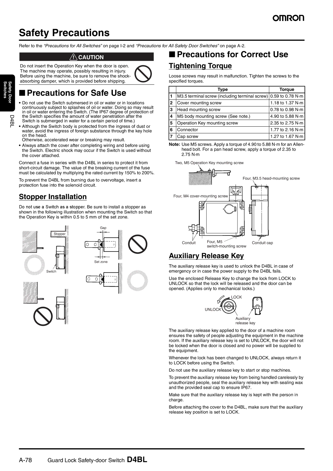
Tightening Torque
Loose screws may result in malfunction. Tighten the screws to the specified torques.
| Type | Torque |
1 | M3.5 terminal screw (including terminal screw) | 0.59 to 0.78 N·m |
|
|
|
2 | Cover mounting screw | 1.18 to 1.37 N·m |
|
|
|
3 | Head mounting screw | 0.78 to 0.98 N·m |
|
|
|
4 | M5 body mounting screw (See note.) | 4.90 to 5.88 N·m |
|
|
|
5 | Operation Key mounting screw | 2.35 to 2.75 N·m |
|
|
|
6 | Connector | 1.77 to 2.16 N·m |
|
|
|
7 | Cap screw | 1.27 to 1.67 N·m |
Note: Use M5 screws. Apply a torque of 4.90 to 5.88 N·m for an Allen- head bolt. For a pan head screw, apply a torque of 2.35 to 2.75 N·m
Two, M5 Operation Key mounting screw
Four, M3.5
Four, M4
Conduit | Four, M5 | Conduit cap |
|
|
Auxiliary Release Key
The auxiliary release key is used to unlock the D4BL in case of emergency or in case the power supply to the D4BL fails.
Use the enclosed Release Key to change the lock from LOCK to UNLOCK so that the lock will be released and the door can be opened. (Applies only to mechanical locks.)
LOCK
UNLOCK
Auxiliary release key
The auxiliary release key applied to the door of a machine room ensures the safety of people adjusting the equipment in the machine room. If the auxiliary release key is set to UNLOCK, the door will not be locked when the door is closed and no power will be supplied to the equipment.
Whenever the lock has been changed to UNLOCK, always return it to LOCK before using the Switch.
Do not use the auxiliary release key to start or stop machines.
To prevent the auxiliary release key from being handled carelessly by unauthorized people, seal the auxiliary release key with sealing wax and the provided seal cap to ensure IP67.
Make sure that the auxiliary release key is kept with the person in charge.
Before attaching the cover to the D4BL, make sure that the auxiliary release key position is set to LOCK.