■Circuit Connection Example
•Terminals 11 and 32 are connected internally and so connect terminals 12 and 31 for
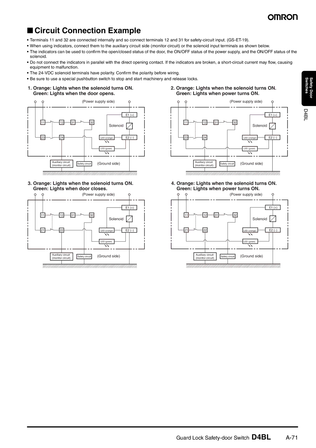
•When using indicators, connect them to the auxiliary circuit side (monitor circuit) or the solenoid input terminals as shown below.
•The indicators can be used to confirm the open/closed status of the door, the ON/OFF status of the power supply, and the ON/OFF status of the solenoid.
•Do not connect the indicators in parallel with the direct opening contact. If the indicators are broken, a
•The
•Be sure to use a special pushbutton switch to stop and start machinery and release locks.
1. Orange: Lights when the solenoid turns ON. |
|
|
| 2. Orange: Lights when the solenoid turns ON. | ||||||||||||||||||||||||||||||||||||||||||||||||||||
Green: Lights when the door opens. |
|
|
|
|
|
|
| Green: Lights when power turns ON. |
|
|
|
| ||||||||||||||||||||||||||||||||||||||||||||
|
|
|
|
|
|
|
|
|
|
|
| (Power supply side) |
|
|
|
|
|
|
|
|
|
|
|
|
|
|
|
|
|
|
| (Power supply side) |
|
|
|
| ||||||||||||||||||||
|
|
|
|
|
|
|
|
|
|
|
|
|
|
|
|
|
|
|
|
|
|
|
|
|
|
|
|
|
|
|
|
|
|
|
|
|
|
|
|
|
|
|
|
|
|
|
|
|
|
|
|
|
|
|
|
|
|
|
|
|
|
|
|
|
|
|
|
|
|
|
|
|
|
|
|
|
|
|
|
|
|
|
|
|
|
|
|
|
|
|
|
|
|
|
|
|
|
|
|
|
|
|
|
|
|
|
|
|
|
|
|
| |
|
|
|
|
|
|
|
|
|
|
|
|
|
|
|
|
|
|
|
|
|
|
| E1 (+) |
|
|
|
|
|
|
|
|
|
|
|
|
|
|
|
|
|
|
|
|
|
|
|
|
|
| E1 (+) | ||||||
|
|
|
|
|
|
|
|
|
|
|
|
|
|
|
|
|
|
|
|
|
|
|
|
|
|
|
|
|
|
|
|
|
|
|
|
|
|
|
|
|
|
|
|
|
|
|
|
|
|
|
|
|
|
|
|
|
| 11 |
|
|
| 12 |
|
| 31 |
|
|
| 32 |
| Solenoid |
|
|
|
|
|
|
|
| 11 |
| 12 |
|
| 31 |
|
| 32 |
|
| Solenoid |
|
|
|
| ||||||||||||||||||
|
|
|
|
|
|
|
|
|
|
|
|
|
|
|
|
|
|
|
|
|
|
|
|
|
|
|
|
|
|
|
| |||||||||||||||||||||||||
|
|
|
|
|
|
|
|
|
|
|
|
|
|
|
|
|
|
|
|
|
|
|
|
|
|
|
|
|
|
|
|
|
|
|
|
|
|
|
|
|
|
|
|
|
|
|
| |||||||||
|
|
|
|
|
|
|
|
|
|
|
|
|
|
|
|
|
|
|
|
|
|
|
|
|
|
|
|
|
|
|
|
|
|
|
|
|
|
|
|
|
|
|
|
|
|
|
| |||||||||
|
|
|
|
|
|
|
|
|
|
|
|
|
|
|
|
|
|
|
|
|
|
|
|
|
|
|
|
|
|
|
|
|
|
|
|
|
|
|
|
|
|
|
|
|
|
|
|
|
|
|
|
|
|
|
|
|
|
|
|
|
|
|
|
|
|
|
|
|
|
|
|
|
|
|
|
|
|
|
|
|
|
|
|
|
|
|
|
|
|
|
|
|
|
|
|
|
|
|
|
|
|
|
|
|
|
|
|
|
|
|
|
|
|
| 23 |
| 24 |
|
|
|
|
|
|
|
|
|
|
| LED (orange) |
|
|
| E2 (−) |
|
|
|
| 23 |
| 24 |
|
|
|
|
|
|
|
|
|
|
| LED (orange) |
|
| E2 (−) | |||||||||||||||
|
|
|
|
|
|
|
|
|
|
|
|
|
|
|
|
|
|
|
|
|
|
|
|
|
|
|
|
|
|
|
|
|
|
|
|
|
|
|
|
|
|
|
|
|
|
|
|
|
|
|
|
|
|
|
|
|
|
|
|
|
|
|
|
|
|
|
|
|
|
|
|
|
|
|
|
|
|
|
|
|
|
|
|
|
|
|
|
|
|
|
|
|
|
|
|
|
|
|
|
|
|
|
|
|
|
|
|
|
|
|
|
|
|
|
|
|
|
|
|
|
|
|
|
|
|
|
|
|
|
|
| LED (green) |
|
|
|
|
|
|
|
|
|
|
|
|
|
|
|
|
|
|
|
|
|
|
|
|
|
|
|
| LED (green) |
|
|
|
|
| ||||
|
|
|
|
|
|
|
|
|
|
|
|
|
|
|
|
|
|
|
|
|
|
|
|
|
|
|
|
|
|
|
|
|
|
|
|
|
|
|
|
|
|
|
|
|
|
|
|
|
|
|
|
|
|
|
|
|
|
|
|
|
|
|
|
|
|
|
|
|
|
|
|
|
|
|
|
|
|
|
|
|
|
|
|
|
|
|
|
|
|
|
|
|
|
|
|
|
|
|
|
|
|
|
|
|
|
|
|
|
|
|
|
|
|
|
|
|
|
| Auxiliary circuit |
|
|
| Safety circuit | (Ground side) |
|
|
|
|
|
|
|
|
|
|
|
| Auxiliary circuit |
|
|
| Safety circuit | (Ground side) |
|
|
|
| ||||||||||||||||||||||||
|
|
|
|
| (monitor circuit) |
|
|
|
|
|
|
|
|
|
|
|
|
|
|
| (monitor circuit) |
|
|
|
|
|
|
| ||||||||||||||||||||||||||||
|
|
|
|
|
|
|
|
|
|
|
|
|
|
|
|
|
|
|
|
|
|
|
|
|
|
|
|
|
|
|
|
|
|
|
|
|
|
|
|
|
|
|
|
|
|
|
|
|
|
|
|
|
|
|
|
|
|
|
|
|
|
|
|
|
|
|
|
|
|
|
|
|
|
|
|
|
|
|
|
|
|
|
|
|
|
|
|
|
|
|
|
|
|
|
|
|
|
|
|
|
|
|
|
|
|
|
|
|
|
|
|
|
|
Safety Door Switches D4BL
3.Orange: Lights when the solenoid turns ON.
Green: Lights when door closes.
(Power supply side)
|
|
|
|
| E1 (+) |
11 | 12 | 31 | 32 | Solenoid |
|
|
|
|
|
| |
21 | 22 |
|
| LED (orange) | E2 (−) |
|
|
|
| LED (green) |
|
| Auxiliary circuit |
| Safety circuit | (Ground side) |
|
| (monitor circuit) |
|
| ||
|
|
|
|
|
4.Orange: Lights when the solenoid turns ON.
Green: Lights when power turns ON.
(Power supply side)
|
|
|
|
| E1 (+) |
11 | 12 | 31 | 32 | Solenoid |
|
|
|
|
|
| |
21 | 22 |
|
| LED (orange) | E2 (−) |
|
|
|
| LED (green) |
|
| Auxiliary circuit |
| Safety circuit | (Ground side) |
|
| (monitor circuit) |
|
| ||
|
|
|
|
|
Guard Lock |