DDAA1000/SRM User Guide
Point-to-Multipoint Analog Operation
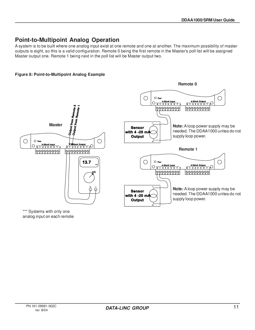
A system is to be built where one analog input exist at one remote and one at another. The maximum possibility of master outputs is eight, so this is a valid configuration. Remote 0 being the first remote in the Master’s poll list will be assigned Master output one. Remote 1 being next in the poll list will be Master output two.
Figure 8: Point-to-Multipoint Analog Example
| 0 | 1 | |
| te | e | |
| t | ||
| o |
| o |
| m |
| m |
e |
| e | |
R |
| R | |
m | m | ||
o |
| o | |
r | fr | ||
Remote 0
![]() Pwr
Pwr
G 1 2 3 4 5 6 7 8 | G 1 2 3 4 5 6 7 8 |
Master | f | t |
t | ||
| u | u |
| p | p |
| t | ut |
| u | |
| O | O |
Pwr |
|
|
G 1 2 3 4 5 6 7 8 | G 1 2 3 4 5 6 7 8 |
13.7
Sensor with 4
Output
![]() Pwr
Pwr
Note: A loop power supply may be needed. The DDAA1000 unites do not supply loop power.
Remote 1
mA
mA
***Systems with only one analog input on each remote
G 1 2 3 4 5 6 7 8 | G 1 2 3 4 5 6 7 8 |
Sensor | Note: A loop power supply may be | |
needed. The DDAA1000 unites do not | ||
with 4 | ||
supply loop power. | ||
Output | ||
|
PN
rev 8/04
11 |
