„Main Circuit Terminals

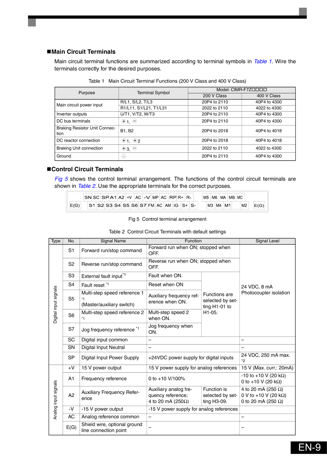
Main circuit terminal functions are summarized according to terminal symbols in Table 1. Wire the terminals correctly for the desired purposes.

Table 1 Main Circuit Terminal Functions (200 V Class and 400 V Class)

Purpose

Terminal Symbol

Model: CIMR-F7Z††††

200 V Class

400 V Class


Main circuit power input

R/L1, S/L2, T/L3

20P4 to 2110

40P4 to 4300

R1/L11, S1/L21, T1/L31

2022 to 2110

4022 to 4300


Inverter outputs

U/T1, V/T2, W/T3

20P4 to 2110

40P4 to 4300

DC bus terminals

1,

20P4 to 2110

40P4 to 4300

Braking Resistor Unit Connec-

B1, B2

20P4 to 2018

40P4 to 4018

tion


DC reactor connection

1, 2

20P4 to 2018

40P4 to 4018

Braking Unit connection

3,

2022 to 2110

4022 to 4300

Ground


20P4 to 2110

40P4 to 4300

„Control Circuit Terminals

Fig 5 shows the control terminal arrangement. The functions of the control circuit terminals are shown in Table 2. Use the appropriate terminals for the correct purposes.

Fig 5 Control terminal arrangement

Table 2 Control Circuit Terminals with default settings

Type

No.

Signal Name

Function


Signal Level


S1

Forward run/stop command

Forward run when ON; stopped when


OFF.


S2

Reverse run/stop command

Reverse run when ON; stopped when


OFF.


S3

External fault input*1

Fault when ON.


signals

S4

Fault reset *1

Reset when ON


24 VDC, 8 mA


S5

Multi-step speed reference 1

Auxiliary frequency ref-


Functions are

Photocoupler isolation

input

*1

erence when ON.


selected by set-


(Master/auxiliary switch)


ting H1-01 to


Digital

S6

Multi-step speed reference 2

Multi-step speed 2


H1-05.


*1

when ON.


S7

Jog frequency reference *1

Jog frequency when


ON.


SC

Digital input common


SN

Digital Input Neutral


SP

Digital Input Power Supply

+24VDC power supply for digital inputs

24 VDC, 250 mA max.


*2


+V

15 V power output

15 V power supply for analog references

15 V (Max. curr.: 20mA)


A1

Frequency reference

0 to +10 V/100%


-10 to +10 V (20 kΩ)

signals


0 to +10 V (20 kΩ)


A2

Auxiliary Frequency Refer-

Auxiliary analog fre-


Function is

4 to 20 mA (250 Ω)

input

ence

quency reference;


selected by set-

0 V to +10 V (20 kΩ)


4 to 20 mA (250Ω)


ting H3-09.

0 to 20 mA (250 Ω)


Analog


-V

-15 V power output

-15 V power supply for analog references


AC

Analog reference common


E(G)

Shield wire, optional ground


line connection point


EN-9

Page 10
Image 10
Omron Healthcare VARISPEEDF7 specifications EN-9, „Main Circuit Terminals, „Control Circuit Terminals

VARISPEEDF7 specifications

The Omron Healthcare VARISPEEDF7 is an innovative and advanced medical device designed to provide effective therapy for various health conditions. This cutting-edge device is part of Omron’s commitment to enhancing healthcare solutions and promoting patient well-being through technology. The VARISPEEDF7 is particularly notable for its versatility and effectiveness in various therapeutic applications.

One of the main features of the VARISPEEDF7 is its adjustable speed settings. This allows healthcare professionals to customize the therapy according to the specific needs of each patient. The ability to vary speed enhances treatment effectiveness, as different conditions may require different intensities. The device is designed to accommodate a wide range of therapeutic needs, making it a valuable tool in clinical and home healthcare settings alike.

The VARISPEEDF7 integrates several advanced technologies, including its proprietary motor control system. This system provides smooth and consistent operation, minimizing disruptions during therapy sessions. The technology ensures precise speed control, enabling healthcare providers to maintain optimal conditions for therapy.

In addition to its speed control, the VARISPEEDF7 is equipped with a user-friendly interface. The display provides clear information about settings and progress, making it easy for both healthcare professionals and patients to monitor treatment sessions. The intuitive design reduces the learning curve and enhances the overall user experience.

Another significant characteristic of the VARISPEEDF7 is its portability. The compact design allows for easy transport and storage, making it ideal for patients who require therapy at home or on the go. This feature is particularly beneficial for individuals with mobility issues or those who enjoy an active lifestyle.

Durability is also a hallmark of the VARISPEEDF7. It is built with high-quality materials that ensure longevity and reliability, even with frequent use. This commitment to durability highlights Omron’s dedication to providing healthcare solutions that practitioners and patients can trust.

In summary, the Omron Healthcare VARISPEEDF7 represents a significant advancement in therapeutic technology. With its adjustable speed settings, advanced motor control system, user-friendly interface, portability, and durability, the VARISPEEDF7 is designed to meet the diverse needs of patients and healthcare providers. It stands out as a versatile solution that enhances patient care and promotes effective treatment outcomes. As healthcare continues to evolve, the VARISPEEDF7 exemplifies how innovative technologies can make a substantial impact on health and well-being.