HT-SP904
Avis
Important Safety Instructions
FCC Information for User
Precautions
Power
For models having a power cord with a polarized plug
Package Contents
Speaker Precautions
Package Contents
Features
Contents
Digital Input Input Display
Setup
Automatic Speaker Setup
Hdmi Video
Front Panel
Getting to Know the AV Receiver
Display
Getting to Know the AV Receiver
Rear Panel
Aiming the Remote Controller
Remote Controller
Installing the Batteries
RECEIVER/TAPE Mode
Remote Controller
Using the Remote Controller
Buttons used when the Tape input is selected
Listening Mode buttons
Remote Mode buttons
Buttons used when the Tuner input is selected
DVD Mode
Arrow / and Enter buttons
CD/MD/CDR/DOCK Mode
To select the input source, press
DISC/ALBUM +/- button
Subwoofer SKW-750
Speakers
Front left and right speakers SKF-750F
Connecting Your Speakers
Using Rubber Spacers with the Speakers
Enjoying Home Theater
Connecting Speakers
Connecting Your Speakers
Speaker Connection Precautions
Using the Speaker Terminal Tool
Mounting vertically
Using the included rubber spacers
Center Speaker Base
Wall Mounting
Attach the FM antenna, as shown
Connecting Antennas
Connecting the AM Loop Antenna
Connecting the Indoor FM Antenna
Using a TV/FM Antenna Splitter
Connecting Antennas
Connecting an Outdoor FM Antenna
Connecting an Outdoor AM Antenna
AV Connection Color Coding
Connecting Your Components
About AV Connections
Optical Digital Jacks
Audio Connection Formats
Connecting Your Components
Connecting Audio and Video Signals to the AV Receiver
Which Connections Should I Use?
Hint
Connecting a TV or Projector
DVD player
Connecting a DVD player
Choose a video connection from a , B , and C
Hooking Up the Multichannel DVD Input
Tip
Connecting Components with Hdmi
Assign the Hdmi
Turn on the AV receiver, and then assign the Hdmi in see
DVD recorder
Connecting a VCR or DVD Recorder for Playback
VCR or DVD recorder
VCR
Make the video connection a Make the audio connection a
Connecting a VCR or DVD Recorder for Recording
Connecting a Camcorder, Games Console, or Other Device
Choose a video connection from a and B
Satellite, cable, set-top box, etc
Video source
CD Player or Turntable MM with Built-in Phono Preamp Step
Connecting a CD Player or Turntable
If Your iPod Doesn’t Support Video
Connecting the DS-A1X RI Dock for the iPod
If Your iPod Supports Video
Cassette/CDR/MD/DAT recorder
Connecting a Cassette, CDR, MiniDisc, or DAT Recorder
Cassette recorder, CDR, etc
Remote Control
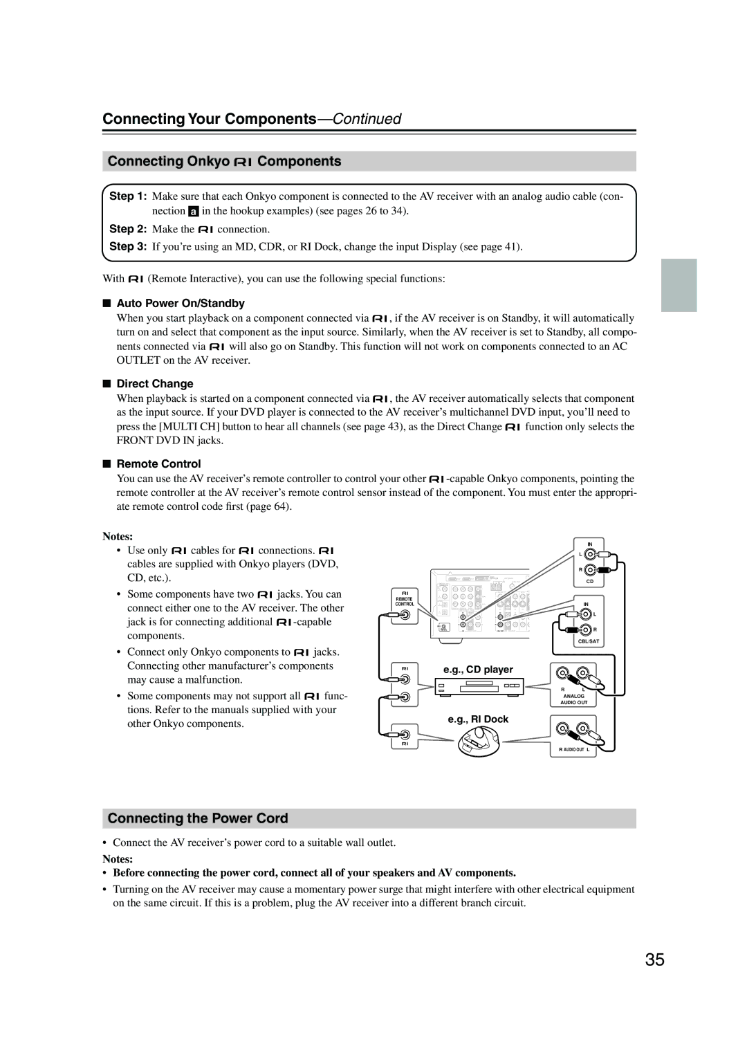
Connecting Onkyo Components
Connecting the Power Cord
Auto Power On/Standby
Smooth Operation in a Few Easy Steps
Turning On the AV Receiver
Turning On and Standby
Measurement Points
First Time Setup
Automatic Speaker Setup Audyssey 2EQ
Using Audyssey 2EQ
First Time Setup
Using a Powered Subwoofer
Error Messages
To Retry the Automatic Speaker Setup
Changing the Speaker Settings Manually
Hdmi Video Setup
Changing the Input Display
Digital Audio Input Setup
Basic AV Receiver Operation
Select a suitable listening mode and enjoy
Playing Your AV Components
Displaying Source Information
Using the Multichannel DVD Input
Playing Your AV Components
Listening to AM/FM Stations
Tuning into AM/FM Radio Stations
Listening to the Radio
Listening to the Radio
Presetting AM/FM Stations
Compatible iPods
DS-A1X Package Contents
DS-A1X RI Dock for the iPod
About the RI Dock
Function Overview
Adjusting the iPod Adapter
DS-A1X RI Dock for the iPod
Putting Your iPod in the RI Dock
Charging Your iPod’s Battery
Using Your iPod’s Alarm Clock
Muting the AV Receiver
Adjusting the Bass and Treble
Setting the Display Brightness
Common Functions
Common Functions
Using the Sleep Timer
Adjusting Speaker Levels
Using Headphones
Selecting Listening Modes
Using the Listening Modes
Selecting with the Remote Controller
This button selects the Stereo listening mode
Stereo
Using the Listening Modes
About the Listening Modes
Direct
DTS
Use this mode when playing game discs
Onkyo Original DSP Modes
Using the Audio Adjust Settings
Using the CinemaFILTER
Using the Late Night Function Dolby Digital only
Listening Angle Setting
Input Channel Settings
Plii Music Mode Settings
DTS Neo6 Music Mode Setting
Recording Audio and Video from Separate Sources
Recording
Recording the Input Source
Speaker Configuration
Advanced Setup
Advanced Speaker Settings
Double Bass
Advanced Setup
Crossover Frequency
Speaker Distance
Pink noise test tone is output by the front left speaker
Setup closes
Speaker Levels
Buttons to select Level Cal, and then press Enter
Buttons to select Equalizer,
Equalizer Settings
Setup menu closes
Correcting Sound and Picture Sync
Digital Input Signal Formats
Controlling Other Components
Entering Remote Control Codes
Controlling Other Components
Remote Control Codes for Onkyo Components Connected via
Resetting Remote Mode Buttons
Resetting the Remote Controller
Operates the VCR
STANDBY/ON, TV
TV VOL
CH +
Troubleshooting
Troubleshooting
Can’t control other components
Remote controller doesn’t work
AV receiver’s remote controller doesn’t control your iPod
Sound changes when I connect my head- phones
Functions don’t work
RI Dock DS-A1X
Specifications
AV Receiver HT-R557
1ch Home Theater Speaker Package HTP-650
Specifications
Onkyo China Limited
Onkyo U.S.A. Corporation
Onkyo Europe Electronics GmbH
Onkyo Europe UK Office