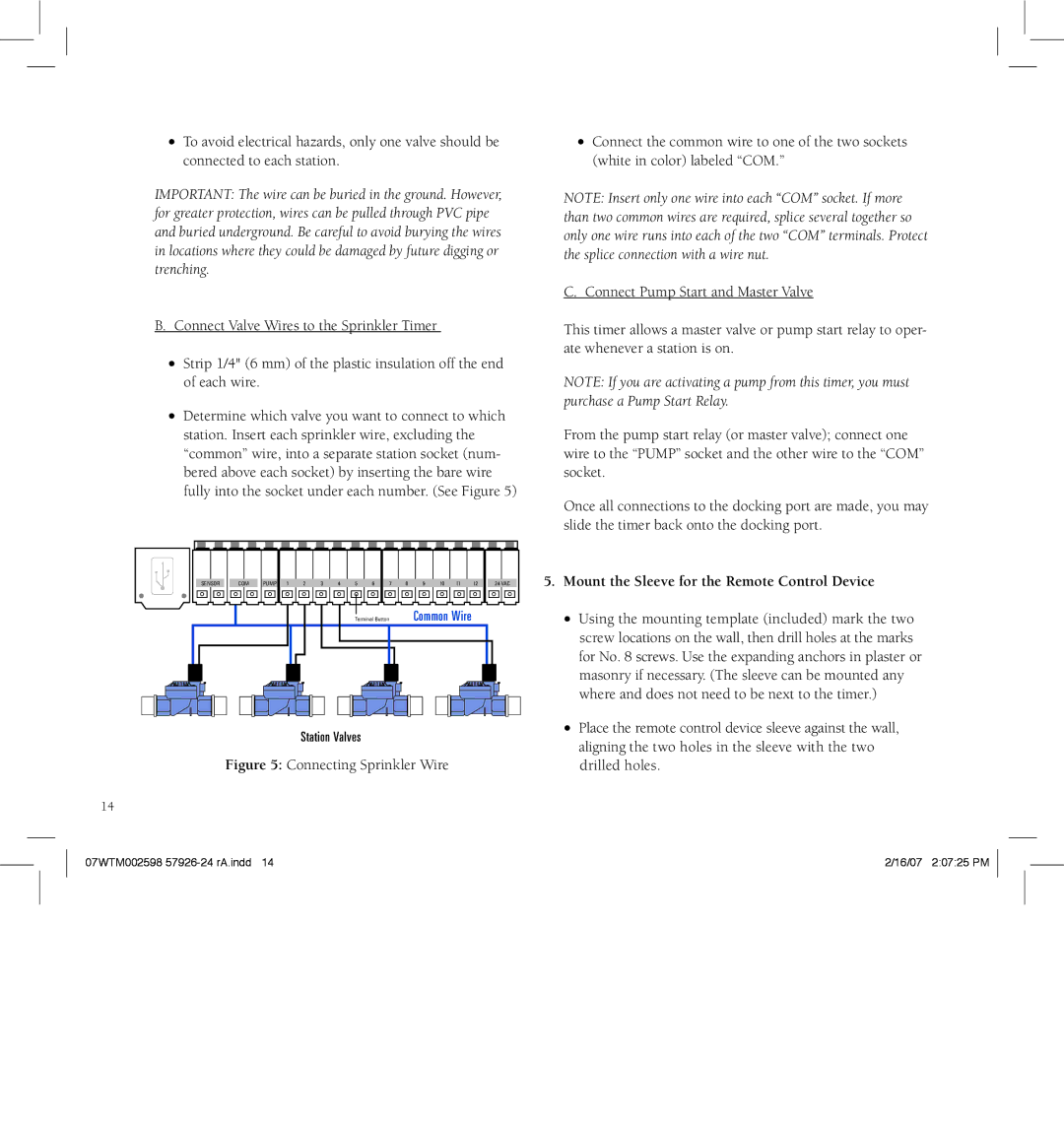
91912, 91926, 94922, f 801 951 5815, 57922 specifications
Orbit Manufacturing is a leading player in the manufacturing sector, known for its innovative and reliable products aimed at enhancing efficiency and productivity. With a wide range of models, including 57916, 57912, 57922, 91912, and 91916, Orbit Manufacturing showcases advanced technology and cutting-edge features suited for diverse applications.The Orbit Manufacturing 57916 model stands out with its robust construction and precision engineering. Designed for high-demand environments, it incorporates advanced automation features, allowing for seamless integration into existing workflows. The model achieves optimal efficiency through its state-of-the-art control systems, minimizing downtime and maximizing output.
The 57912 model focuses on versatility, making it ideal for various manufacturing tasks. It combines flexibility with power, enabling users to adapt to changing production needs quickly. The model also includes advanced diagnostic tools that help operators monitor performance in real time, ensuring proactive maintenance and reducing operational costs.
In the 57922 variant, Orbit Manufacturing emphasizes user-friendly design alongside cutting-edge technology. This model is equipped with an intuitive interface, making it accessible for operators with varying levels of expertise. The 57922’s energy-efficient motors significantly reduce power consumption while maintaining high productivity levels, contributing to lower operational expenses and a more sustainable manufacturing process.
The 91912 model introduces even greater automation capabilities, incorporating AI-driven analytics for predictive maintenance. This feature empowers operators with insights that help preemptively address potential issues, ensuring continuous production flow. The 91912 is recognized for its high-speed performance and durable components, making it a favorite in industries requiring rigorous and continuous operation.
Lastly, the 91916 model builds on this foundation by integrating IoT technologies, enabling real-time data exchange and remote monitoring. This connectivity provides manufacturers with the flexibility to manage operations from virtually anywhere, enhancing responsiveness to market demands. Furthermore, the 91916 model is designed for scalability, allowing businesses to expand their production capabilities without significant reinvestment.
In summary, Orbit Manufacturing's range of models, including 57916, 57912, 57922, 91912, and 91916, showcases the company’s commitment to innovation, efficiency, and adaptability in the manufacturing landscape. Each model boasts unique features and technologies aimed at optimizing production processes, ensuring that clients stay competitive in a rapidly evolving market.

