
AJ-D650 specifications
The Panasonic AJ-D650 is a professional digital video recorder that has garnered attention for its performance and reliability in various broadcast and production environments. This versatile machine supports a range of video formats, making it an essential tool for filmmakers, broadcasters, and video production professionals. Launched as part of Panasonic's DVCPro series, the AJ-D650 stands out for its ability to deliver high-quality images while maintaining user-friendly operation.One of the notable features of the AJ-D650 is its ability to record in both standard-definition (SD) and high-definition (HD) formats. It utilizes the DVCPro video codec, which allows for efficient compression without compromising image quality. This is particularly advantageous for professionals looking to store large volumes of footage without sacrificing clarity or detail, making it an optimal choice for long recording sessions.
The recorder integrates advanced digital audio capabilities, offering 16-bit, 48 kHz audio recording. Stability and reliability are enhanced through its use of high-performance tape transport mechanisms, which are designed to minimize dropouts and achieve consistent playback. This is crucial in live broadcasting environments where precision is paramount.
With built-in time code support, the AJ-D650 facilitates synchronized recording and playback, ensuring accurate timestamping of footage. This feature streamlines the editing process, allowing for smoother production workflows. Additionally, the machine includes comprehensive editing functionalities, accommodating various post-production requirements.
The device is designed for rigorous professional use, featuring a robust construction that can withstand the demands of fieldwork. Its compact form factor, combined with lightweight materials, makes it portable while still ensuring durability.
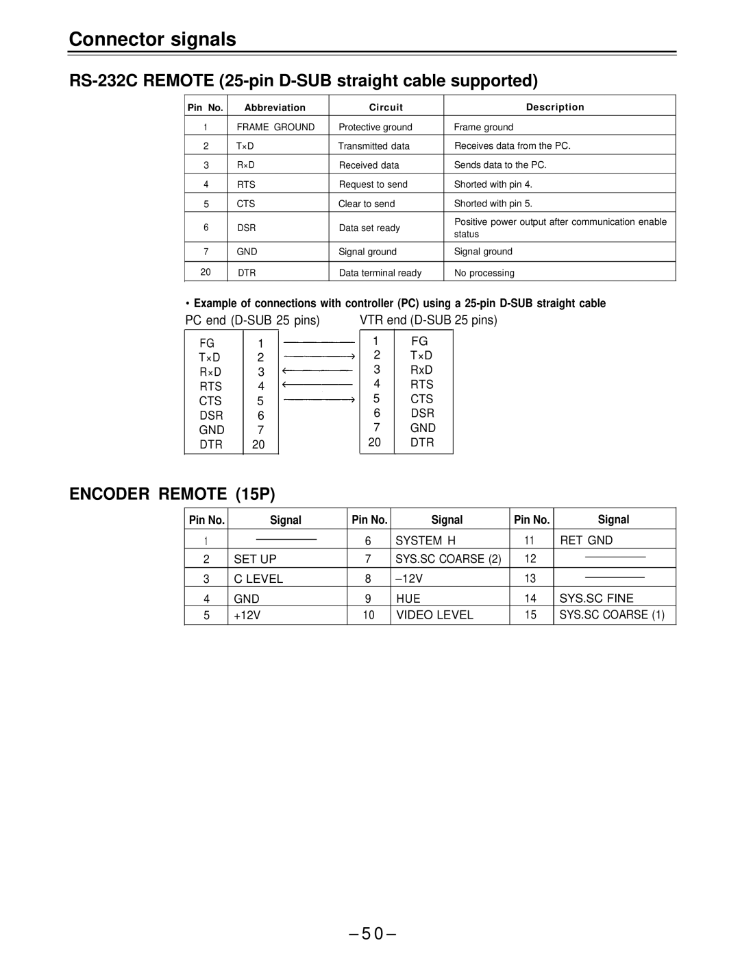
Connectivity options are comprehensive, including multiple input and output ports that facilitate integration with other equipment. These features enhance its adaptability in different production setups, whether in the studio or on location.
In summary, the Panasonic AJ-D650 stands out in the realm of professional digital video recording, combining advanced technology with user-friendly features. Its versatility, robust design, and high-quality output make it a preferred choice for professionals seeking reliability and performance in video production contexts.