11 Installation Instruction
11.1. Select the Best Location
11.1.1.Indoor Unit
•Do not install the unit in excessive oil fume area such as kitchen, workshop and etc.
•There should not be any heat source or steam near the unit.
•There should not be any obstacles blocking the air circulation.
•A place where air circulation in the room is good.
•A place where drainage can be easily done.
•A place where noise prevention is taken into consideration.
•Do not install the unit near the door way.
•Ensure the spaces indicated by arrows from the wall, ceiling, fence or other obstacles.
•Recommended installation height for indoor unit shall be at least 2.5 m.
11.1.2.Outdoor Unit
•If an awning is built over the unit to prevent direct sunlight or rain, be careful that heat radiation from the condenser is not obstructed.
•There should not be any animal or plant which could be affected by hot air discharged.
•Keep the spaces indicated by arrows from wall, ceiling, fence or other obstacles.
•Do not place any obstacles which may cause a short circuit of the discharged air.
•If piping length is over the [piping length for additional gas], additional refrigerant should be added as shown in the table.
|
| Piping |
|
|
|
| Addi- | Piping | ||
|
| size |
| Max. | Min. | Max. | Length | |||
Model | Horse |
|
| Std. | Ele- | Piping | Piping | tional | for | |
|
| |||||||||
Power |
| Li- | Length | vation | Length | Length | Refri- | add. | ||
| (HP) | Gas | (m) | gerant | ||||||
|
|
| quid |
| (m) | (m) | (m) | (g/m) | gas | |
|
|
|
|
|
|
|
| (m) | ||
|
|
|
|
|
|
|
|
| ||
CE9*** | 1.0HP | 3/8” | 1/4” | 5 | 5 | 3 | 15 | 20 | 7.5 | |
|
|
|
|
|
|
|
| |||
CE12*** | 1.5HP | 1/2” | 5 | 3 | 15 | 20 | 7.5 | |||
|
| |||||||||
|
|
|
|
|
|
|
|
|
| |
Example: For CE9***
If the unit is installed at 10 m distance, the quantity of additional refrigerant should be 50 g ....
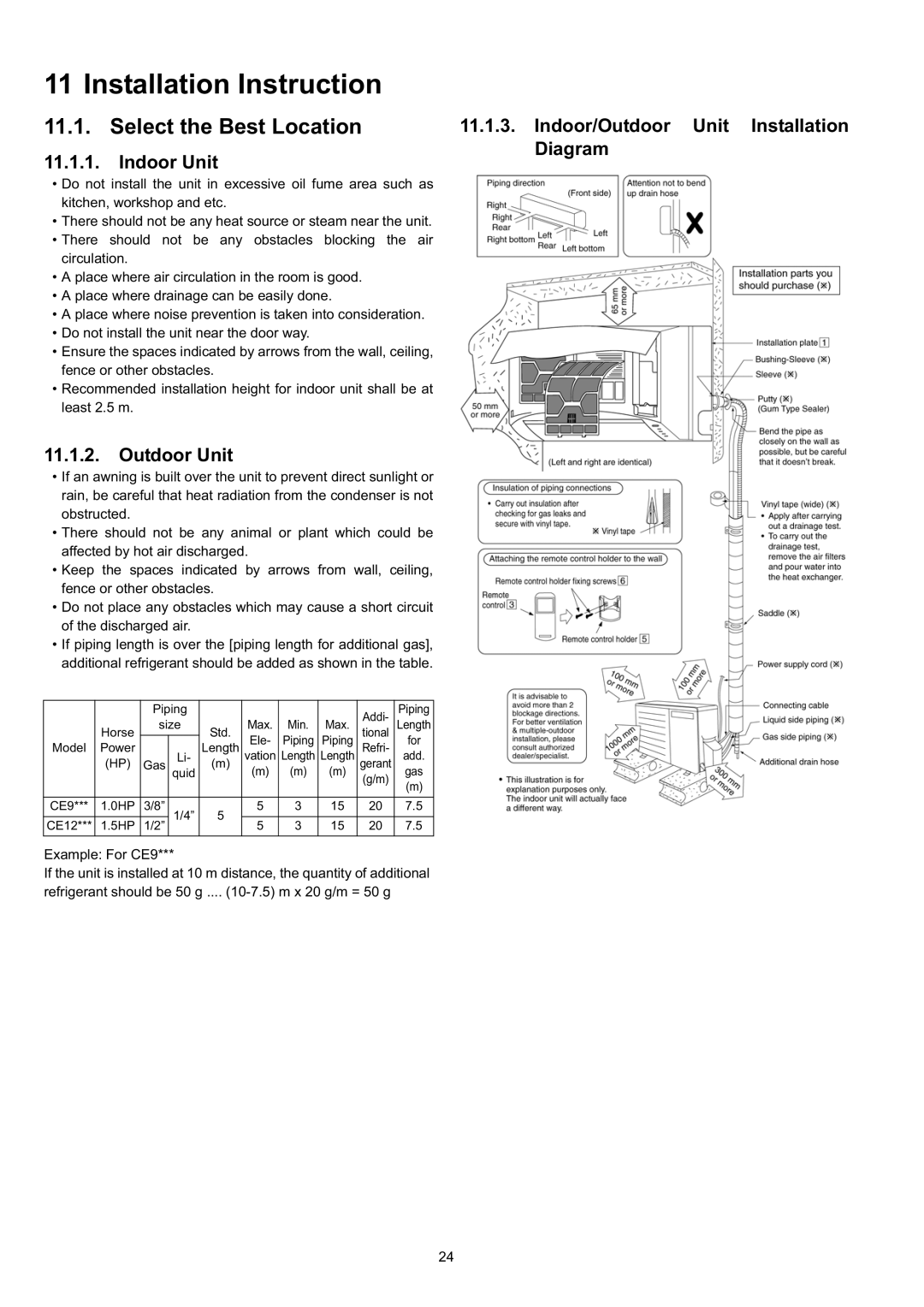
11.1.3.Indoor/Outdoor Unit Installation Diagram
24