Manuals
/
Panasonic
/
Household Appliance
/
Air Conditioner
Panasonic
CS-CE9JKE
specifications
Models:
CS-CE9JKE
1
1
2
3
4
5
6
7
8
9
10
11
12
13
14
15
16
17
18
19
20
21
22
23
24
25
26
27
28
29
30
31
32
33
34
35
36
37
38
39
40
41
42
43
44
45
46
47
48
49
50
51
52
53
54
55
56
57
58
59
60
61
62
63
64
65
66
67
68
69
70
71
72
73
74
75
76
77
78
79
80
81
82
83
84
84
Download
84 pages
47.05 Kb
64
65
66
67
68
69
70
71
72
73
Troubleshooting
Specification
Operation Characteristics
Install
Error messages
Refrigeration Cycle Diagram
Timer Control
Dimension
Reset RC
Safety Precautions
Page 69
Image 69
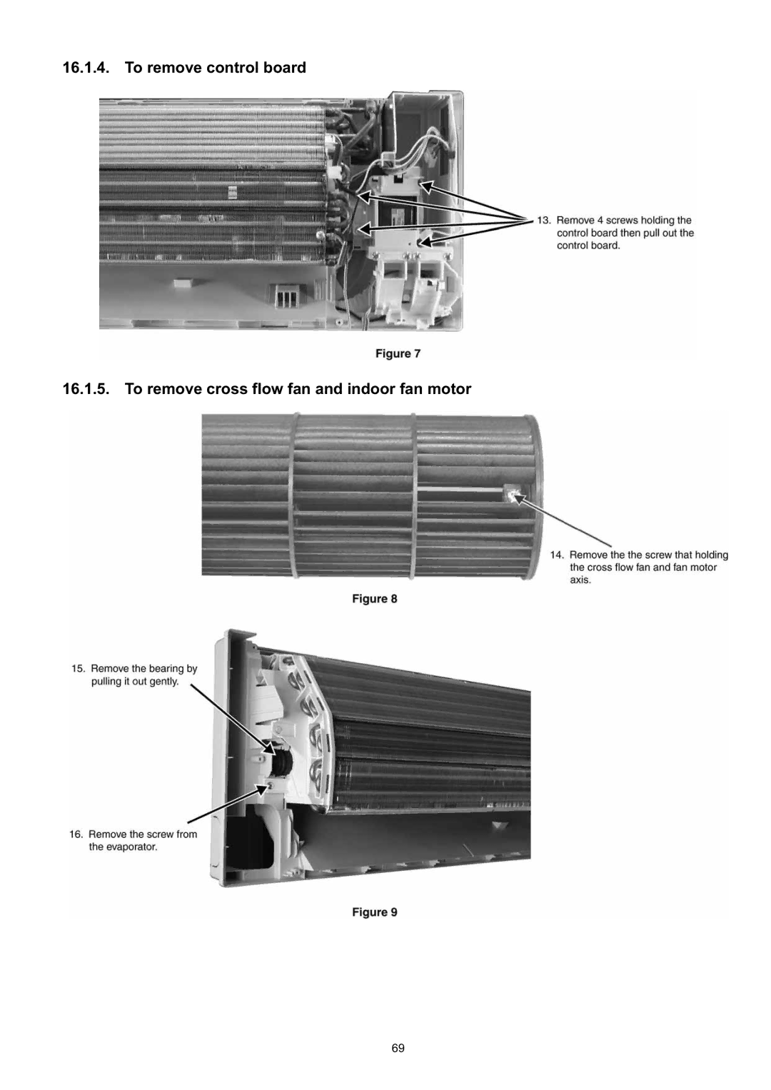
16.1.4. To remove control board
16.1.5. To remove cross flow fan and indoor fan motor
69
Page 68
Page 70
Page 69
Image 69
Page 68
Page 70
Contents
Table of Contents
Exploded View and Replacement Parts List
Safety Precautions
Page
Model Indoor CS-CE9JKE Outdoor CU-CE9JKE
Specifications
Type Propeller Fan Material Motor Type
Model Indoor CS-CE9JKE Outdoor CU-CE9JKE
Model Indoor CS-CE12JKE Outdoor CU-CE12JKE
Cool/Fan M3/min ft3/min
Model Indoor CS-CE12JKE Outdoor CU-CE12JKE
Easy to use remote control Quality Improvement
Features
Location of Controls and Components
Indoor Unit Outdoor Unit Remote Control
Indoor Unit
Dimensions
Outdoor Unit
Refrigeration Cycle Diagram
Block Diagram
Wiring Connection Diagram
Outdoor Unit
Electronic Circuit Diagram
Outdoor Unit
Main Printed Circuit Board
Printed Circuit Board
Power Printed Circuit Board Indicator Printed Circuit Board
Outdoor Unit
Indoor/Outdoor Unit Installation Diagram
Installation Instruction
Select the Best Location
Indoor Unit
How to Fix Installation Plate
To Drill a Hole in the Wall and Install Sleeve of Piping
Indoor Unit Installation
This can be used for left rear piping and bottom piping also
Cutting and Flaring the Piping
Connect the Cable to the Indoor Unit
Install the Outdoor Unit
Connect the Piping
Evacuation of the Equipment
Pipe Insulation
Connect the Cable to the Outdoor Unit
Basic Function
Operation and Control
Indoor Fan Motor Operation
Automatic Operation
Fan Operation
Outdoor Fan Motor Operation
Airflow Direction
Vertical Airflow
Timer Control
Auto Restart Control
Indication Panel
Protection Control For All Operations
Protection Control
Compressor Overheating Prevention Control
Low Pressure Prevention Control Gas Leakage Detection
Low Frequency Protection Control
Protection Control For Cooling & Soft Dry Operation
Outdoor Air Temperature Control
Cooling Overload Control
Freeze Prevention Control
Protection Control For Heating Operation
Auto OFF/ON Button
Servicing Mode
Reset RC
Remote Control Button
Reset AC
Timer
Refrigeration Cycle System
Troubleshooting Guide
Low Pressure High Pressure
Self Diagnosis Function Three Digits Alphanumeric Code
Breakdown Self Diagnosis Function
Protection control Judgement
Error Codes Table
Power source or compressor lock
15.4.1. H11 Indoor/Outdoor Abnormal Communication
Self-diagnosis Method
15.4.2. H14 Indoor Intake Air Temperature Sensor Abnormality
15.4.3. H15 Compressor Temperature Sensor Abnormality
15.4.4. H16 Outdoor Current Transformer Open Circuit
15.4.5. H19 Indoor Fan Motor DC Motor Mechanism Locked
15.4.6. H23 Indoor Pipe Temperature Sensor Abnormality
15.4.7. H27 Outdoor Air Temperature Sensor Abnormality
15.4.8. H28 Outdoor Pipe Temperature Sensor Abnormality
Malfunction Decision Conditions
15.4.10. H33 Unspecified Voltage between Indoor and Outdoor
15.4.11. H97 Outdoor Fan Motor DC Motor Mechanism Locked
15.4.12. H98 Indoor High Pressure Protection
Malfunction Caused
15.4.14. F11 4-way valve Abnormality
15.4.15. F90 Power Factor Correction Protection
Multi Models Only
15.4.16. F91 Refrigeration Cycle Abnormality
15.4.17. F93 Compressor Rotation Failure
15.4.18. F95 Cooling High Pressure Abnormality
15.4.19. F96 IPM Overheating
15.4.20. F97 Compressor Overheating
15.4.21. F98 Input Over Current Detection
15.4.22. F99 Output Over Current Detection
To remove front grille To remove power electronic controller
Disassembly and Assembly Instructions
To remove discharge grille
Page
Page
Outdoor Electronic Controller Removal Procedure
Technical Data
Operation Characteristics
CU-CE9JKE
Page
Page
Page
CU-CE12JKE
Page
Page
Page
CU-CE12JKE
Sensible Capacity Chart
Exploded View and Replacement Parts List
Chassy Complete
Outdoor Unit
Chassy ASS’Y
Top
Page
Image
Contents