VCR and Cable Box Connection (Cont.)
Recording a premium (scrambled) cable channel
Procedure
• Press the TV/VIDEO button and the numeric keys on the |
remote control to select the video input (VIDEO 1, |
OPTIONAL EQUIPMENT CONNECTIONS
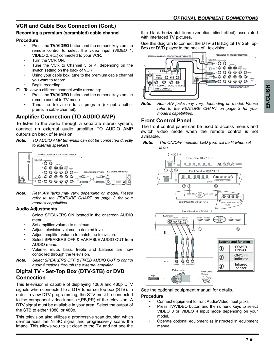
thin black horizontal lines (venetian blind effect) associated with interlaced TV pictures.
Use this diagram to connect the
VIDEO 2, etc.) connected to your VCR. |
• Turn the VCR ON. |
• Tune the VCR to Channel 3 or 4, depending on the |
switch setting on the back of VCR. |
• Using your cable box, tune to the premium cable channel |
you want to record. |
• Begin recording. |
To view a different channel while recording: |
• Press the TV/VIDEO button and the numeric keys on the |
remote control to TV mode. |
TERMINALS ON BACK OF
| DIGITAL TV OUTPUT | |||
R- | Y | PB | PR | |
MAIN |
|
| ||
VIDEO |
|
| ||
| ||||
| NTSC OUTPUT |
|
| |
|
| TERMINALS ON BACK OF TELEVISION | |||||
|
| COMPONENT |
|
|
|
|
|
| HDMI | VIDEO INPUT | 1 | 2 |
|
|
|
| AV IN | Y |
|
|
|
|
|
|
|
|
|
| |||
|
|
|
|
|
| ||
|
| PB |
|
|
| VIDEO |
|
|
|
|
|
| INPUT | PROG | |
|
|
|
|
|
| ||
|
|
|
|
|
|
| OUT |
|
| PR |
|
|
|
| VIDEO |
ANT |
| L |
|
|
|
| L |
|
|
|
|
|
|
| TO AUDIO |
|
| IN |
|
|
|
| AMP |
|
| R |
|
|
|
| R |
|
|
|
| 1 | 2 | 3 |
|
CABLES NOT INCLUDED
• Tune the television to | a program (except another |
premium cable channel). |
|
Amplifier Connection (TO AUDIO AMP)
To listen to the audio through a separate stereo system, connect an external audio amplifier TO AUDIO AMP outputs on back of television.
Note: TO AUDIO AMP terminals can not be connected directly to external speakers.
|
| CONNECTIONS ON BACK OF TELEVISION |
|
| |||
|
| COMPONENT |
|
|
|
|
|
| HDMI | VIDEO INPUT 1 | 2 |
|
|
|
|
| AV IN | Y |
|
|
|
|
|
|
|
|
|
| |||
|
|
|
|
|
| ||
|
| PB |
|
| VIDEO |
|
|
|
|
|
| INPUT PROG |
|
| |
|
|
|
|
|
|
| |
|
|
|
|
| OUT |
|
|
|
| PR |
|
| VIDEO | CABLES NOT SUPPLIED | EXTERNAL AMPLIFIER |
ANT |
| L |
|
| L |
|
|
|
| AUDIO |
|
| TO AUDIO |
|
|
|
| IN |
|
| AMP |
|
|
|
| R |
|
| R |
| 90.7 MHZ |
|
|
| 1 | 2 | 3 |
|
|
Note: Rear A/V jacks may vary, depending on model. Please refer to the FEATURE CHART on page 3 for your model’s capabilities.
Audio Adjustments
• Select SPEAKERS ON located in the onscreen AUDIO |
menu. |
• Set amplifier volume to minimum. |
• Adjust television volume to desired level. |
• Adjust amplifier volume to match the television. |
• Select SPEAKERS OFF & VARIABLE AUDIO OUT from |
Note: Rear A/V jacks may vary, depending on model. Please refer to the FEATURE CHART on page 3 for your model’s capabilities.
Front Control Panel
The front control panel can be used to access menus and switch video mode when the remote control is not available.
Note: The ON/OFF indicator LED (red) will be lit when set is on.
1 | 2 | 3 |
|
|
|
|
| Front Panel |
| ||
POWER |
|
|
|
|
|
|
|
|
|
| INPUT 3 |
|
| VOLUME | CHANNEL | ACTION TV/VIDEO | |
1 | 2 | 3 | Front Panel for |
|
|
|
POWER |
|
|
|
|
ACTION TV/VIDEO | VOL +/ | </ | CH >/ | |
|
|
|
| |
|
|
|
| INPUT 4 |
2 | 1 |
|
| 3 |
|
| CH |
|
POWER VOL | ACT ION | VOL TV / VIDEO | |
CH
Front Panel for | |||
|
|
| INPUT 3 |
Front Panel for |
|
| |
|
|
| |
VIDEO 4 L - AUDIO - R | POWER TV/VIDEO | CH | BBE |
ACTION | |||
| VOL |
| VOL |
|
| CH |
|
2 | 1 |
| 3 |
AUDIO menu. |
• Volume, mute, bass, treble and balance are now |
controlled through the television. |
Note: Select SPEAKERS OFF & FIXED AUDIO OUT to control audio functions through the external amplifier.
OUTPUT |
|
|
VIDEO | L - AUDIO - R |
Buttons and function
1 | POWER | |
ON/OFF | ||
| ||
2 | ON/OFF | |
indicator | ||
| ||
3 | Infrared | |
sensor | ||
|
Digital TV - Set-Top Box (DTV-STB) or DVD Connection
Palmcorder
VCR
Video Game Console
This television is capable of displaying 1080i and 480p DTV signals when connected to a DTV tuner
This television also utilizes a progressive scan doubler, which
or | or |
See the optional equipment manual for details.
Procedure
•Connect equipment to front Audio/Video input jacks.
•Press TV/VIDEO button and the numeric keys to select VIDEO 3 or VIDEO 4 input mode depending on your model.
•Operate optional equipment as instructed in equipment manual.
7z