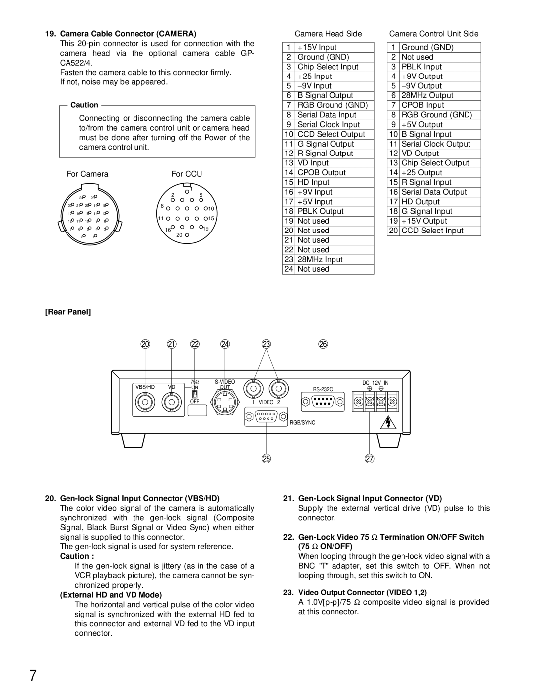
19.Camera Cable Connector (CAMERA)
This
Fasten the camera cable to this connector firmly. If not, noise may be appeared.
Caution
Connecting or disconnecting the camera cable to/from the camera control unit or camera head must be done after turning off the Power of the camera control unit.
For Camera | For CCU | ||||||
|
|
|
|
|
| 1 | |
| 24 |
| 23 |
| 2 | 5 | |
|
|
|
|
| |||
22 | 21 | 20 | 19 | 18 | 6 | 10 | |
|
|
|
|
|
| ||
17 | 16 | 15 | 14 | 13 | 11 | 15 | |
12 | 11 | 10 | 9 | 8 | |||
|
| ||||||
7 | 6 | 5 | 4 | 3 | 16 | 19 | |
| 2 |
| 1 |
|
| 20 | |
|
|
|
|
| |||
[Rear Panel]
| Camera Head Side |
|
|
1 | +15V Input |
2 | Ground (GND) |
3 | Chip Select Input |
4 | +25 Input |
5 | − 9V Input |
6 | B Signal Output |
7 | RGB Ground (GND) |
8 | Serial Data Input |
9 | Serial Clock Input |
10 | CCD Select Output |
11 | G Signal Output |
12 | R Signal Output |
13 | VD Input |
14 | CPOB Output |
15 | HD Input |
16 | +9V Input |
17 | +5V Input |
18 | PBLK Output |
19 | Not used |
20 | Not used |
21 | Not used |
22 | Not used |
23 | 28MHz Input |
24 | Not used |
Camera Control Unit Side
1 | Ground (GND) |
2 | Not used |
3 | PBLK Input |
4 | +9V Output |
5 | − 9V Output |
6 | 28MHz Output |
7 | CPOB Input |
8 | RGB Ground (GND) |
9 | +5V Output |
10 | B Signal Input |
11 | Serial Clock Output |
12 | VD Output |
13 | Chip Select Output |
14 | +25 Output |
15 | R Signal Input |
16 | Serial Data Output |
17 | HD Output |
18 | G Signal Input |
19 | +15V Output |
20 | CCD Select Input |
VBS/HD | VD | 75Ω | DC 12V IN | |
ON | OUT | |||
|
|
|
| |
|
| OFF | 1 | VIDEO 2 |
RGB/SYNC
20.Gen-lock Signal Input Connector (VBS/HD)
The color video signal of the camera is automatically synchronized with the
The
Caution :
If the
(External HD and VD Mode)
The horizontal and vertical pulse of the color video signal is synchronized with the external HD fed to this connector and external VD fed to the VD input connector.
21.Gen-Lock Signal Input Connector (VD)
Supply the external vertical drive (VD) pulse to this connector.
22.Gen-Lock Video 75 Ω Termination ON/OFF Switch (75 Ω ON/OFF)
When looping through the
23.Video Output Connector (VIDEO 1,2)
A
7