KX-TC2000NZB / KX-TC2000N ZW / KX-TC2000NZF
19.4. Charge Circuit
Circuit Operation:
When charging the handset on the base unit, the charge current is as follows;
DC (JK2) → L8 → D6 → Q14 → Q24 → L7 → CHG+(Base) → [CHG+(Handset) → L4 → Q9 → BATT(1)....Battery....BATT(2)
→ L5 →
In this way, the CPU on both unit detects the fact that the battery is charged.
The charge current is controlled by switching Q24, Q25 of Base Unit. The battery is charged in normal mode for 15 hours and then in trickle mode.
19.5. Telephone Line Interface
Function:
∙Bell signal detection
∙ON/OFF hook and pulse dial circuit
∙Side tone circuit
Bell signal detection and OFF HOOK circuit:
In the idle mode, Q103 is open to cut the DC loop current and decrease the ring load. When ring voltage appears at the Tip (T) and Ring (R) leads (When the telephone rings), the AC ring voltage is transferred as follows:
JK1 (3): T → L6 → R184 → R144 → IC3D (12,13 → 14) → C97 → R148 → Q20 → IC2 (24) [BELL]
JK1 (2): R → L4 → R183 → R152 →−
When the CPU (DSP) detects a ring signal and press the TALK Key on the handset. Q6 turns on and then RY1 turns on, thus providing an
T → R160 → L4 → D2 → RY1 → R107 → T7 → R116 → D5 → L6 → R161 → R [OFF HOOK]
ON HOOK Circuit:
Q6 is open, RY1 disconnected as to cut the DC loop current and to cut the voice signal. The unit is consequently in an
Side Tone Circuit:
Basically this circuit prevents the TX signal from feeding back to RX signal.
As for this unit, TX signal feed back from Q11 is canceled by the cancellor circuit of AGC.
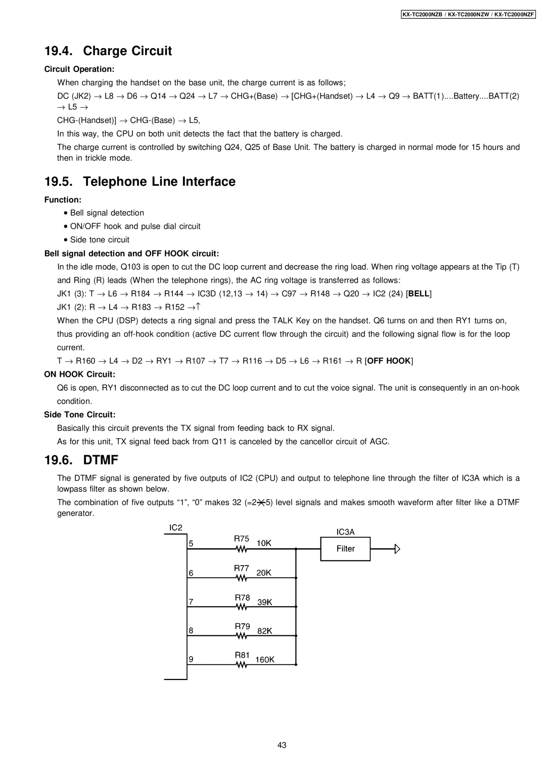
19.6. DTMF
The DTMF signal is generated by five outputs of IC2 (CPU) and output to telephone line through the filter of IC3A which is a lowpass filter as shown below.
The combination of five outputs “1”, “0” makes 32 (=2 ![]() 5) level signals and makes smooth waveform after filter like a DTMF generator.
5) level signals and makes smooth waveform after filter like a DTMF generator.
43