Linked Timer Recordings by External Equipments (EXT LINK)
If an external equipment (for example a satellite receiver) with a timer function is connected to the AV2 socket of this VCR by a
Make sure that [AV2] is set to [EXT LINK 1] or [EXT LINK 2]. (See page 21.)
Timer programming has to be done and switch to the timer recording standby mode on the external equipment, refer to its operating instructions.
1)Press the [EXT LINK] (48) on the VCR to switch the VCR over to the timer recording standby mode.
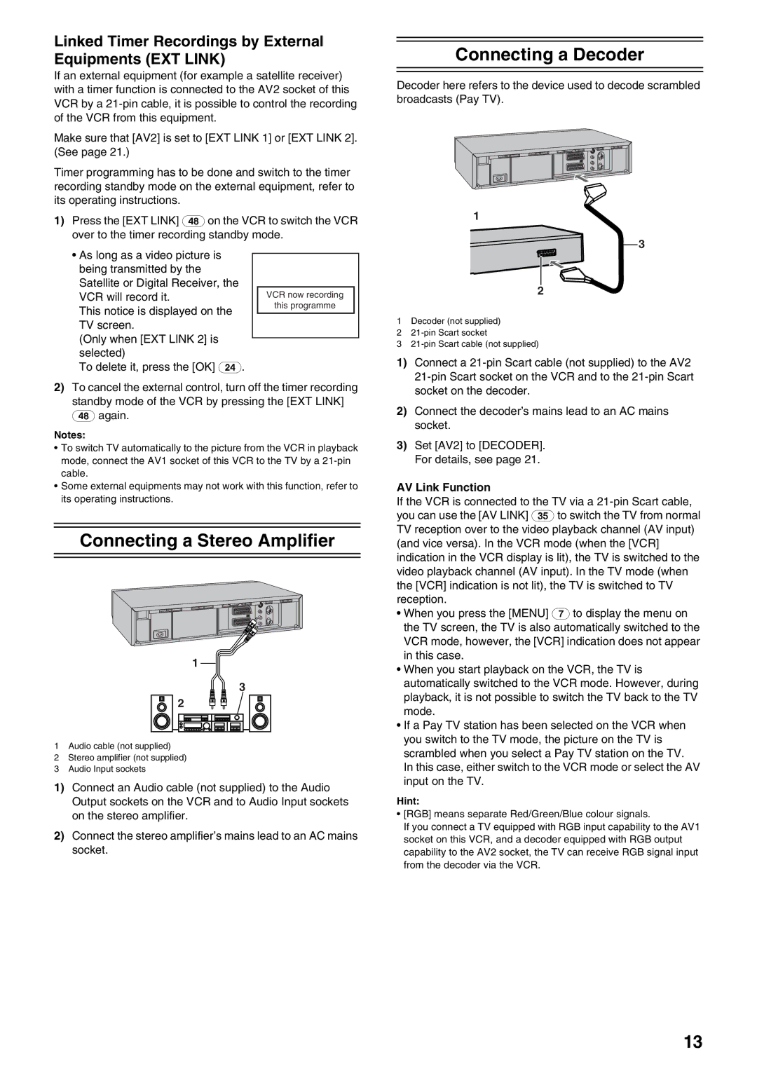
Connecting a Decoder
Decoder here refers to the device used to decode scrambled broadcasts (Pay TV).
1
3
•As long as a video picture is being transmitted by the Satellite or Digital Receiver, the VCR will record it.
This notice is displayed on the TV screen.
(Only when [EXT LINK 2] is selected)
To delete it, press the [OK] (24).
VCR now recording
this programme
2
1Decoder (not supplied)
2
3
1) Connect a |
2)To cancel the external control, turn off the timer recording standby mode of the VCR by pressing the [EXT LINK] (48) again.
Notes:
•To switch TV automatically to the picture from the VCR in playback mode, connect the AV1 socket of this VCR to the TV by a
•Some external equipments may not work with this function, refer to its operating instructions.
Connecting a Stereo Amplifier
1
3 2 ![]()
![]()
![]()
1Audio cable (not supplied)
2Stereo amplifier (not supplied)
3Audio Input sockets
1)Connect an Audio cable (not supplied) to the Audio Output sockets on the VCR and to Audio Input sockets on the stereo amplifier.
2)Connect the stereo amplifier’s mains lead to an AC mains socket.
| socket on the decoder. |
2) | Connect the decoder’s mains lead to an AC mains |
| socket. |
3) | Set [AV2] to [DECODER]. |
| For details, see page 21. |
AV Link Function
If the VCR is connected to the TV via a
•When you press the [MENU] (7) to display the menu on the TV screen, the TV is also automatically switched to the VCR mode, however, the [VCR] indication does not appear in this case.
•When you start playback on the VCR, the TV is automatically switched to the VCR mode. However, during playback, it is not possible to switch the TV back to the TV mode.
•If a Pay TV station has been selected on the VCR when you switch to the TV mode, the picture on the TV is scrambled when you select a Pay TV station on the TV.
In this case, either switch to the VCR mode or select the AV input on the TV.
Hint:
•[RGB] means separate Red/Green/Blue colour signals.
If you connect a TV equipped with RGB input capability to the AV1 socket on this VCR, and a decoder equipped with RGB output capability to the AV2 socket, the TV can receive RGB signal input from the decoder via the VCR.
13