Appendix
List of compatible signals
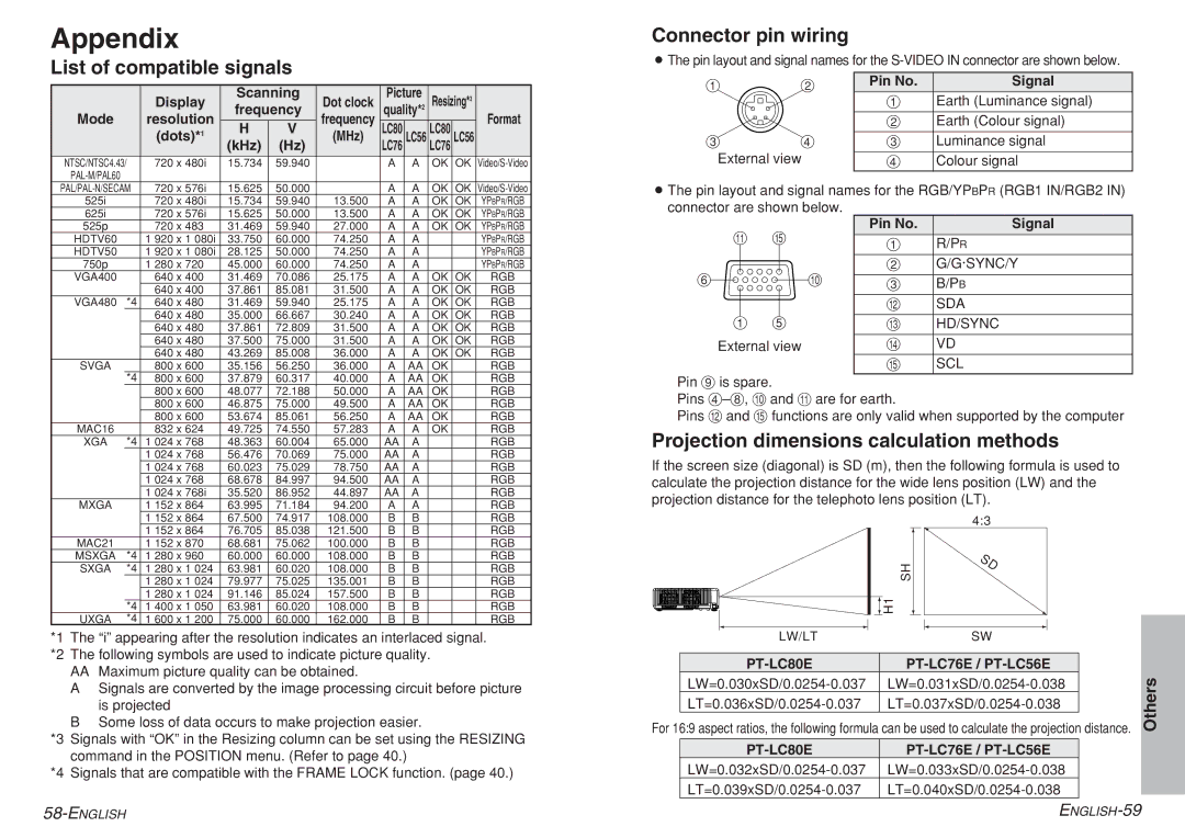
Connector pin wiring
BThe pin layout and signal names for the
| Display | Scanning | Dot clock | Picture2 | Resizing*3 | ||||
Mode | resolution | frequency | frequency | quality* |
|
| Format | ||
H | V | LC80 |
| LC80 |
| ||||
| (dots)*1 | (MHz) | LC56 | LC56 | |||||
|
| (kHz) | (Hz) |
| LC76 |
| LC76 |
|
|
NTSC/NTSC4.43/ | 720 x 480i | 15.734 | 59.940 |
| A | A | OK | OK | |
|
|
|
|
|
|
|
|
| |
#$
%&
External view
Pin No. | Signal |
#Earth (Luminance signal) $ Earth (Colour signal)
% Luminance signal & Colour signal
720 x 576i | 15.625 | 50.000 |
| A | A | OK OK | |||
525i |
| 720 x 480i | 15.734 | 59.940 | 13.500 | A | A | OK OK YPBPR/RGB | |
625i |
| 720 x 576i | 15.625 | 50.000 | 13.500 | A | A | OK OK YPBPR/RGB | |
525p |
| 720 x 483 | 31.469 | 59.940 | 27.000 | A | A | OK OK YPBPR/RGB | |
HDTV60 |
| 1 920 x 1 080i | 33.750 | 60.000 | 74.250 | A | A |
| YPBPR/RGB |
HDTV50 |
| 1 920 x 1 080i | 28.125 | 50.000 | 74.250 | A | A |
| YPBPR/RGB |
750p |
| 1 280 x 720 | 45.000 | 60.000 | 74.250 | A | A |
| YPBPR/RGB |
VGA400 |
| 640 x 400 | 31.469 | 70.086 | 25.175 | A | A | OK OK | RGB |
|
| 640 x 400 | 37.861 | 85.081 | 31.500 | A | A | OK OK | RGB |
VGA480 | *4 | 640 x 480 | 31.469 | 59.940 | 25.175 | A | A | OK OK | RGB |
|
| 640 x 480 | 35.000 | 66.667 | 30.240 | A | A | OK OK | RGB |
|
| 640 x 480 | 37.861 | 72.809 | 31.500 | A | A | OK OK | RGB |
|
| 640 x 480 | 37.500 | 75.000 | 31.500 | A | A | OK OK | RGB |
|
| 640 x 480 | 43.269 | 85.008 | 36.000 | A | A | OK OK | RGB |
SVGA |
| 800 x 600 | 35.156 | 56.250 | 36.000 | A | AA | OK | RGB |
| *4 | 800 x 600 | 37.879 | 60.317 | 40.000 | A | AA | OK | RGB |
|
| 800 x 600 | 48.077 | 72.188 | 50.000 | A | AA | OK | RGB |
|
| 800 x 600 | 46.875 | 75.000 | 49.500 | A | AA | OK | RGB |
|
| 800 x 600 | 53.674 | 85.061 | 56.250 | A | AA | OK | RGB |
MAC16 |
| 832 x 624 | 49.725 | 74.550 | 57.283 | A | A | OK | RGB |
XGA | *4 | 1 024 x 768 | 48.363 | 60.004 | 65.000 | AA | A |
| RGB |
|
| 1 024 x 768 | 56.476 | 70.069 | 75.000 | AA | A |
| RGB |
|
| 1 024 x 768 | 60.023 | 75.029 | 78.750 | AA | A |
| RGB |
|
| 1 024 x 768 | 68.678 | 84.997 | 94.500 | AA | A |
| RGB |
|
| 1 024 x 768i | 35.520 | 86.952 | 44.897 | AA | A |
| RGB |
MXGA |
| 1 152 x 864 | 63.995 | 71.184 | 94.200 | A | A |
| RGB |
|
| 1 152 x 864 | 67.500 | 74.917 | 108.000 | B | B |
| RGB |
|
| 1 152 x 864 | 76.705 | 85.038 | 121.500 | B | B |
| RGB |
MAC21 |
| 1 152 x 870 | 68.681 | 75.062 | 100.000 | B | B |
| RGB |
MSXGA | *4 | 1 280 x 960 | 60.000 | 60.000 | 108.000 | B | B |
| RGB |
SXGA | *4 | 1 280 x 1 024 | 63.981 | 60.020 | 108.000 | B | B |
| RGB |
|
| 1 280 x 1 024 | 79.977 | 75.025 | 135.001 | B | B |
| RGB |
|
| 1 280 x 1 024 | 91.146 | 85.024 | 157.500 | B | B |
| RGB |
| *4 | 1 400 x 1 050 | 63.981 | 60.020 | 108.000 | B | B |
| RGB |
UXGA | *4 | 1 600 x 1 200 | 75.000 | 60.000 | 162.000 | B | B |
| RGB |
*1 The “i” appearing after the resolution indicates an interlaced signal. *2 The following symbols are used to indicate picture quality.
AA Maximum picture quality can be obtained.
ASignals are converted by the image processing circuit before picture is projected
BSome loss of data occurs to make projection easier.
*3 Signals with “OK” in the Resizing column can be set using the RESIZING command in the POSITION menu. (Refer to page 40.)
*4 Signals that are compatible with the FRAME LOCK function. (page 40.)
BThe pin layout and signal names for the RGB/YPBPR (RGB1 IN/RGB2 IN)
connector are shown below. | Pin No. | Signal | ||
- | 1 | |||
# | R/PR | |||
|
| |||
|
| $ | G/G·SYNC/Y | |
( | , | % | B/PB | |
|
| . | SDA | |
# | ' | / | HD/SYNC | |
External view | 0 | VD | ||
|
| 1 | SCL | |
Pin + is spare.
Pins
Pins . and 1 functions are only valid when supported by the computer
Projection dimensions calculation methods
If the screen size (diagonal) is SD (m), then the following formula is used to calculate the projection distance for the wide lens position (LW) and the projection distance for the telephoto lens position (LT).
|
|
|
| 4:3 |
| |||||
|
|
|
|
| SH |
| ||||
|
|
|
|
| H1 |
|
|
|
| |
|
|
|
|
|
| |||||
|
|
|
|
|
| |||||
|
|
|
|
|
|
|
|
|
|
|
|
|
|
|
|
|
|
|
|
|
|
| LW/LT |
|
|
|
|
|
|
| SW |
|
|
|
|
|
|
| |||||
|
|
|
|
|
| |||||
For 16:9 aspect ratios, the following formula can be used to calculate the projection distance.
Others