Adjustment motor open/closed | Motor control units, |
| |||
The adjustment motor is mounted directly on the flat | |||||
axis. It is equipped with a universal terminal block and | with operating light. The motor is protected by connect- | ||||
is fastened into place with a locking piston supplied with | ing thermal contacts. |
|
|
| |
the unit. | Should a problem occur (when the thermal contacts are | ||||
| |||||
The drive has a mechanism protecting it from overload- | activated), the internal main contactor lapses and inter- | ||||
ing and requires no final switch. For manual operation, | rupts the power supply to the motor. After the cause of | ||||
the transmission can be automatically disengaged using | the problem has been removed, the speed selector can | ||||
the automatic reset knob. | be reset. |
|
|
|
|
Wiring diagram | It is possible to connect the control units to a room ther- | ||||
mostat that switches the unit on and off. |
| ||||
|
| ||||
|
|
|
|
|
|
| Switching | Voltage | Power | Protection | Weight |
| type | ||||
| unit | V | A | kg | |
| IP | ||||
|
|
|
|
| |
|
|
|
|
|
|
| RTRD 2.5 | 400 | 2.5 | 54 | 10.5 |
|
|
|
|
|
|
| RTRD 4.5 | 400 | 4.5 | 54 | 15.1 |
|
|
|
|
|
|
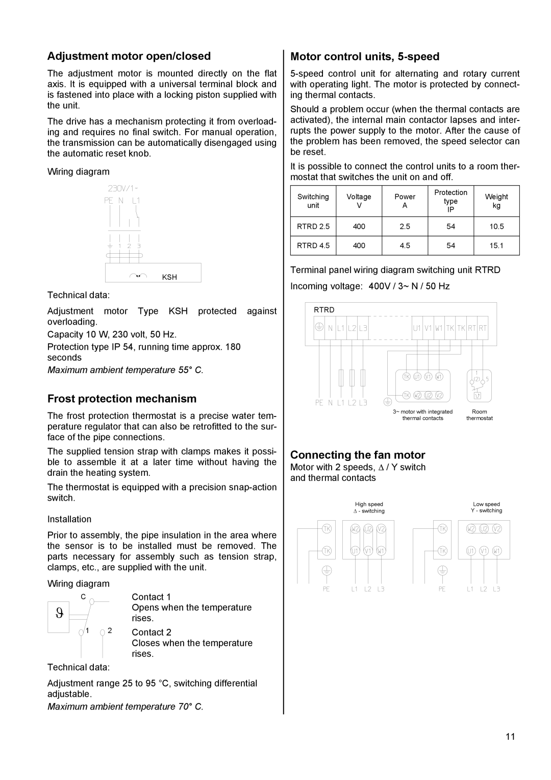
KSH | Terminal panel wiring diagram switching unit RTRD | ||
Incoming voltage: | 400V / 3~ N / 50 Hz | ||
Technical data: | |||
|
| ||
Adjustment motor Type KSH protected against | RTRD |
| |
overloading. |
|
| |
Capacity 10 W, 230 volt, 50 Hz. |
|
| |
Protection type IP 54, running time approx. 180 |
|
| |
seconds |
|
| |
Maximum ambient temperature 55° C.
Frost protection mechanism |
|
|
The frost protection thermostat is a precise water tem- | 3~ motor with integrated | Room |
thermal contacts | thermostat | |
perature regulator that can also be retrofitted to the sur- |
|
|
face of the pipe connections. |
|
|
The supplied tension strap with clamps makes it possi- | Connecting the fan motor |
|
ble to assemble it at a later time without having the | Motor with 2 speeds, ∆ / Y switch |
|
drain the heating system. |
| |
and thermal contacts |
| |
The thermostat is equipped with a precision |
| |
|
| |
switch. | High speed | Low speed |
| ||
Installation | ∆ - switching | Y - switching |
|
|
Prior to assembly, the pipe insulation in the area where the sensor is to be installed must be removed. The parts necessary for assembly such as tension strap, clamps, etc., are supplied with the unit.
Wiring diagram
CContact 1
ϑ |
| Opens when the temperature |
|
| rises. |
1 | 2 | Contact 2 |
|
| Closes when the temperature |
|
| rises. |
Technical data:
Adjustment range 25 to 95 °C, switching differential adjustable.
Maximum ambient temperature 70° C.
11