Sample Assemblies
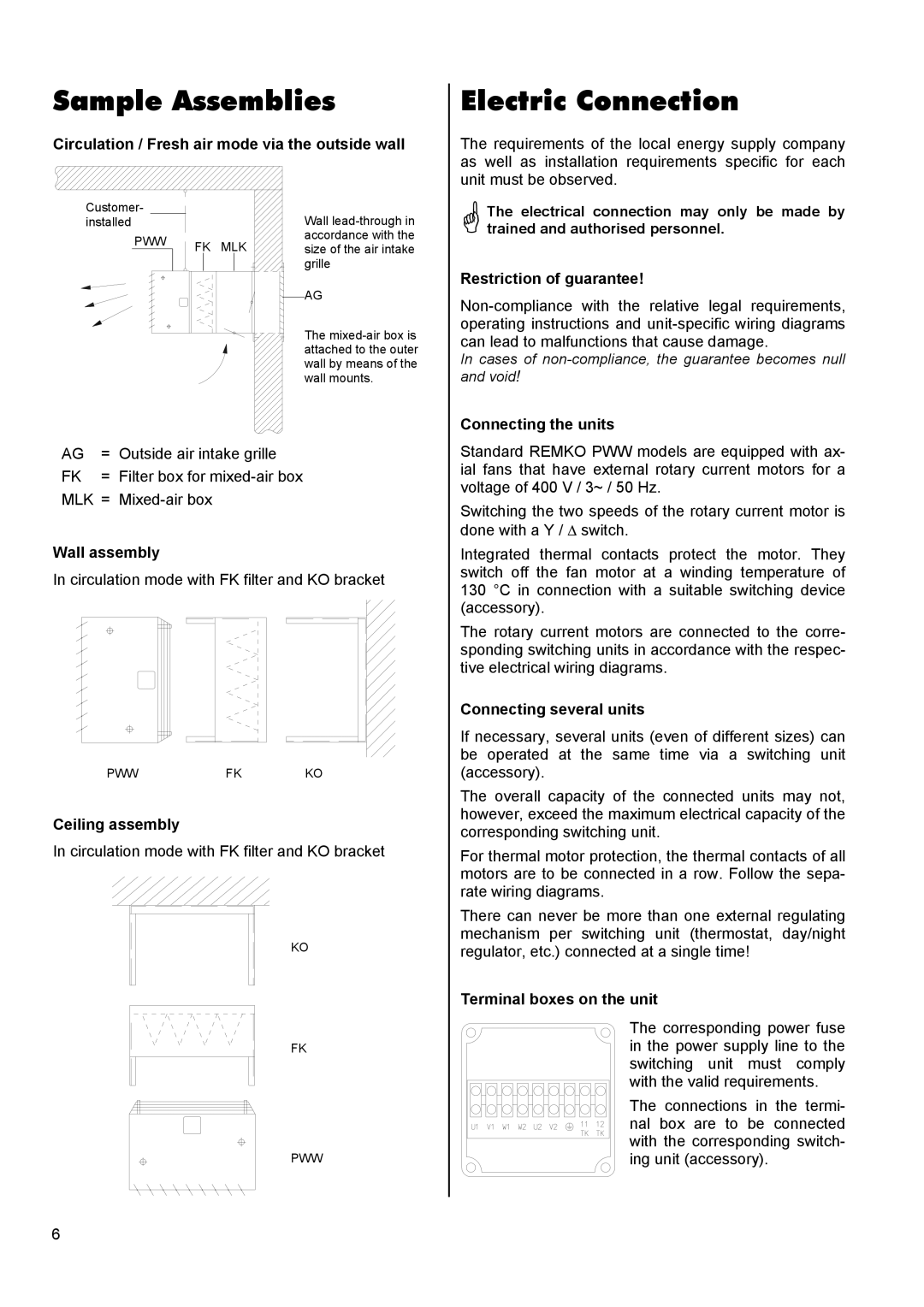
Circulation / Fresh air mode via the outside wall
Electric Connection
The requirements of the local energy supply company as well as installation requirements specific for each
Customer- |
|
|
installed |
|
|
PWW | FK | MLK |
|
Wall
AG
The
unit must be observed.
The electrical connection may only be made by trained and authorised personnel.
Restriction of guarantee!
In cases of
Connecting the units
AG | = | Outside air intake grille |
FK | = | Filter box for |
MLK | = | |
Wall assembly
In circulation mode with FK filter and KO bracket
PWW | FK | KO |
Ceiling assembly
In circulation mode with FK filter and KO bracket
KO
FK
PWW
Standard REMKO PWW models are equipped with ax- ial fans that have external rotary current motors for a voltage of 400 V / 3~ / 50 Hz.
Switching the two speeds of the rotary current motor is done with a Y / ∆ switch.
Integrated thermal contacts protect the motor. They switch off the fan motor at a winding temperature of 130 °C in connection with a suitable switching device (accessory).
The rotary current motors are connected to the corre- sponding switching units in accordance with the respec- tive electrical wiring diagrams.
Connecting several units
If necessary, several units (even of different sizes) can be operated at the same time via a switching unit (accessory).
The overall capacity of the connected units may not, however, exceed the maximum electrical capacity of the corresponding switching unit.
For thermal motor protection, the thermal contacts of all motors are to be connected in a row. Follow the sepa- rate wiring diagrams.
There can never be more than one external regulating mechanism per switching unit (thermostat, day/night regulator, etc.) connected at a single time!
Terminal boxes on the unit
The corresponding power fuse in the power supply line to the switching unit must comply with the valid requirements.
The connections in the termi- nal box are to be connected with the corresponding switch- ing unit (accessory).
6