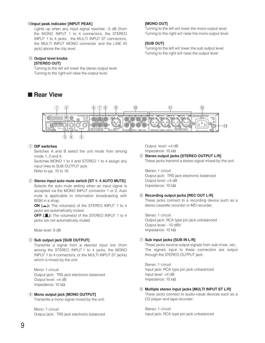
WR-XS3P specifications
The Panasonic WR-XS3P is a cutting-edge wearable technology designed to enhance the way users interact with their environments while promoting health and wellness. At the forefront of its features, this smartwatch combines advanced health monitoring capabilities with practical smart technology, making it a valuable companion for fitness enthusiasts and tech-savvy individuals alike.One of the standout features of the WR-XS3P is its comprehensive health monitoring system. Equipped with a state-of-the-art heart rate sensor, the device provides real-time heart rate tracking to help users optimize their workouts and overall health. Additionally, the smartwatch includes an advanced sleep tracking feature, which allows users to monitor their sleep patterns and gain insights into their sleep quality, enabling them to make informed lifestyle choices.
The WR-XS3P also boasts built-in GPS functionality, allowing users to track their outdoor activities without needing to carry a phone. Whether running, cycling, or hiking, this feature provides accurate distance and pace measurements, giving users the data they need to improve their performance. Coupled with its companion smartphone app, users can analyze their activity history and set personalized goals for better health management.
In terms of connectivity, the Panasonic WR-XS3P is designed to integrate seamlessly with smartphones, offering notifications for calls, messages, and social media alerts directly on the wrist. This functionality empowers users to stay connected while keeping their mobile devices tucked away, promoting a more focused lifestyle.
The smartwatch’s sleek and modern design ensures that it remains stylish and functional. It features a high-resolution display that provides clear visibility in various lighting conditions, alongside customizable watch faces to suit individual preferences. Additionally, its durable construction ensures that it can withstand daily wear, making it an ideal choice for active users.
Battery life is another strong suit of the WR-XS3P, with the device offering several days of use on a single charge. This longevity makes it a reliable companion for both everyday tasks and intensive workout sessions.
In conclusion, the Panasonic WR-XS3P is more than just a smartwatch; it is a comprehensive health and activity tracker equipped with modern technology that caters to the needs of today’s consumers. With its health monitoring features, built-in GPS, seamless connectivity, stylish design, and impressive battery life, the WR-XS3P stands out as a top choice for anyone looking to elevate their fitness and tech experience.

