Color Cctv Camera
English Version
Important Safety Instructions
English
Disclaimer of Warranty
Limitation of Liability
Optional Accesories
Features
Accesories
Precautions
Operating Precautions
Self-diagnosing Function
Contents
Construction
Ensuring Trouble-free Operation
Installation Precautions
Beware of high humidity
DIP Switch Settings
Communication Parameters DIP Switch
Unit Number DIP Switch
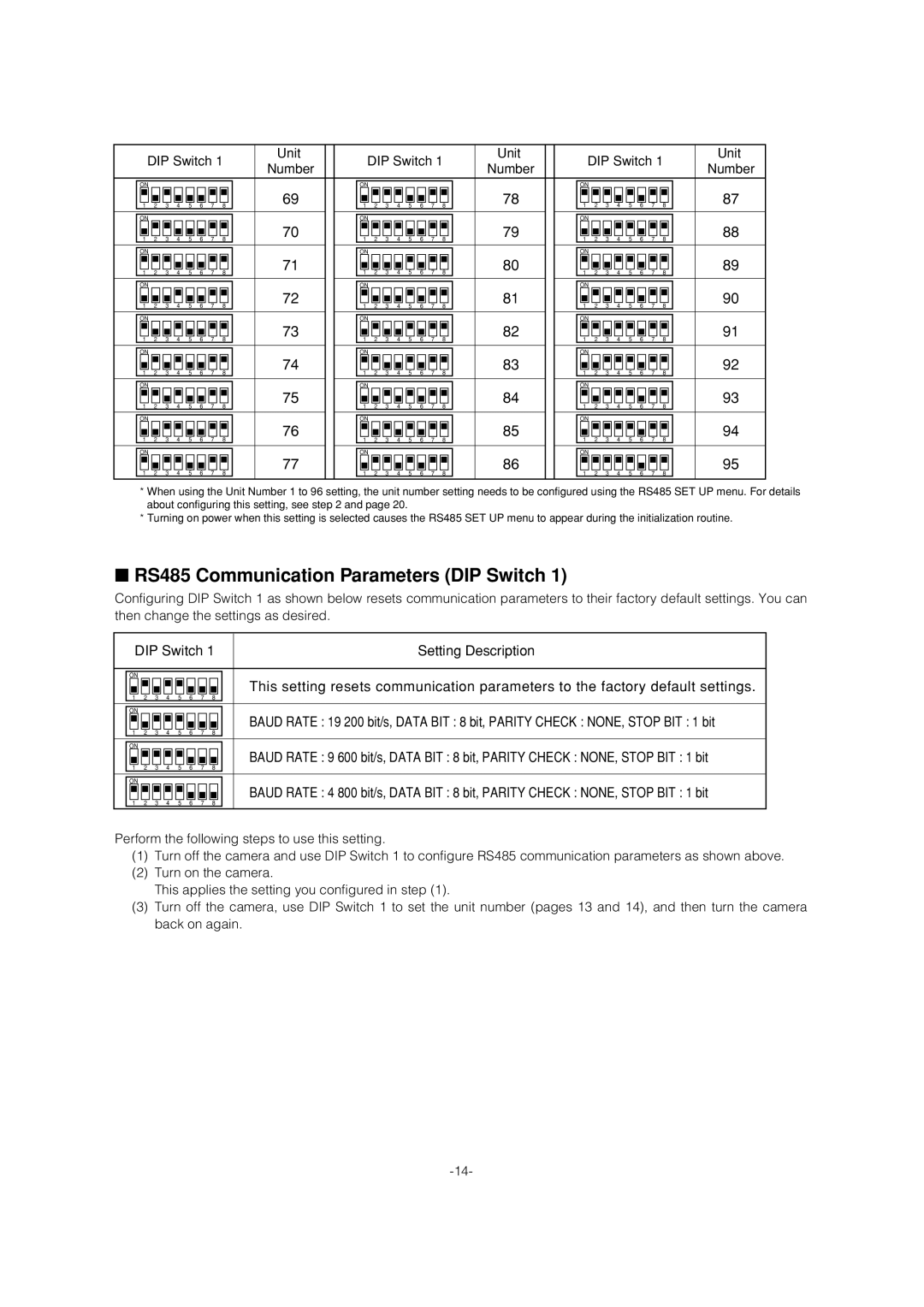
RS485 Communication Parameters DIP Switch
DIP Switch Unit Number
Camera Installation
Installing the Camera
Back
Removing the Decorative Camera
Uninstalling the Camera
Uninstalling the Camera
Connections
How to Assemble the Cable with the Accessory Connector
Connect this to 24 V AC Class 2 Power Supply only
USE
RS485 Setup
Enables X ON/X OFF data flow control
AUTO1
Language Setting
Using the Setup Menu
Displaying the Setup Menu
When using the WV-CU650
ALC
Camera Settings
Using the Camera Setup Menu
Shutter Speed Shutter
When SUPER-D 3 is turned off
When SUPER-D 3 is turned on
OFF ↔ Auto
OFF
Adjusting the Phase for Line-lock Synchronization
On MID
Between the color mode and the black
Resolution Resolution
Black and White Mode BW Mode
White mode in accordance with picture
Zoom Limit Zoom Limit
Auto Focus AF Mode
Example
Auto Image Stabilizer Stabilizer
Position Number Selection Preset
Using the Pan/Tilt Setup Menu
Position Setting Position SET
PAN / Tilt
Preset ID Setting Preset ID
Scene File Setting Scene File
Auto Focus AF Mode
Preset Speed Setting Preset Speed
Light Control ALC/MANUAL
Deleting a Preset Position DEL
Configuring Auto PAN Detailed Settings
PAN Limit
Auto PAN Key Setting Auto PAN KEY
Patrol Function Setting Patrol
Privacy Zone Setting Privacy Zone
Image Hold Setting Image Hold
Area Title Setting Area Title
Digital Flip Setting Digital Flip
Proportional Pan/Tilt Setting PROPO. P/T
On User
Tilt Angle Setting Tilt Angle
Cleaning Settings Cleaning
Configuring Detailed Motion Detector Settings for Mode
Alarm Settings
Using the Alarm Setup Menu
Mode
PATROL1
1POSI
Autopan
PATROL2
Alarm
2POSI
3POSI
Adjusting Picture Quality
Special Settings
Using the Special Setup Menu
To delete a blemish compensation pattern
Scene Select Settings
Scene Select Setting
Using the Scene Select Setting Menu
Quick Menu Settings
Displaying the Quick Setup Menu
Turning Password Lock On and Off
Password Settings
Password Lock Settings
Changing the Password
OK Reset RET TOP
Controller Operation Setting
Shortcuts
Iris Close
Troubleshooting
FIX
Problem
37-38 36-37
Periodically check the power cord and plug
Pan and Tilt
Specifications
General
Lens
Main Functions
Version Français
Instructions DE Sécurité Importantes
Limitation DE Responsabilité
Déni DE LA Garantie
Déni DE LA Garantiecaractéristiques
Accessoires
Accessoires EN Option
Mesures DE Précautions
Ne pas mouiller la caméra
Précautions Pendant LE Fonctionnement
Que faire si le message Over Heat apparaît sur l’écran
Nettoyage de la caméra vidéo
Fonction d’auto-diagnostic
Réglages DE LA Caméra Vidéo
Installation DE LA Caméra Vidéo
Utilisation DU Menu DE Configuration
PAN/AZIMUTH
Objectif ’objectif ne peut pas être remplacé
Fonctionnement sans problème
Les vis doivent être commandées séparément
Précautions Pour L’INSTALLATION
Emplacement et installation de la caméra
Câblage de la caméra vidéo
Émission de chaleur
Réglages DES Interrupteurs DIP
Paramètres de communications Interrupteur DIP
Degré d’humidité élevé
Numéro de caméra vidéo déterminé Interrupteur DIP
Caméra
Paramètres de communication RS485 Interrupteur DIP
Interrupteur DIP Numéro de
Installation DE LA Caméra Vidéo
Installation de la caméra vidéo
Bague du fil de sécurité
Enlever la caméra vidéo
Enlever LA Caméra
Retrait du couvercle décoratif
Branchements
Capacités entrée/sortie d’alarme
Informations relatives aux connecteurs accessoires
Mesures de précautions
Comment assembler le câble et le connecteur acces- soire
Active le contrôle de flux de données
RS485 Ajust
Utilise
ON/X OFF
Réglage de langue
Utilisation DU Menu DE Configuration
Affichage du menu de configuration
Réglages DE LA Caméra Vidéo
Utilisation du menu de réglage de la Caméra
OUI
OUI Eleve
OUI BAS
OUI Moyen
Sélectionne le mode noir et blanc
Résolution Résolution
Mode noir et blanc Mode NB
Sélectionne le mode couleur
Limite de réglage de zoom Limite Zoom
Mode de mise au point automatique Mode AF
Exemple
Stabilisateur d’images automatique
PAN/AZIMUTH
Sélection du numéro de position Prepo
ZOOM/FOCUS
PAN/AZIMUTH
Contrôle de lumière ALC/MANUEL
TRI
Orig
SÉQ
Suiv
Configuration des réglages détaillés d’AUTO PAN
Demarage
Limit PAN
PAN/AZIMUTH ∑BOUTON SET ZOOM/FOCUS ∑BOUTON SET
Maintien d’Image Image Memo
12 Réglage du titre de zone Titre Zone
Titre Zoneutil
14 Réglages de nettoyage Nettoyage
Réglages DE L’ALARME
Utilisation du menu de réglage de ’alarme
1POSITION
PATR1
3POSITION
2POSITION
PATR2
PATR3
Pour effacer un motif de compensation d’imperfections
Réglages Spéciaux
Utilisation du menu de réglage spécial
Auto Élevé BAL BLC PERM2
Réglage DE Sélection DE Scène
Utilisation du menu de réglage de Sélection de scène
Réglages DU Menu Rapide
Affichage du menu de réglage rapide
Réglages DU MOT DE Passe
Réglages du verrouillage du mot de Passe MOT DE Passe
Nouveau MOT PASSE?
Raccourcis
Opération du contrôleur Réglage
Iris Fermer
EN CAS DE Problèmes
Problème
Cause et action recommandée
88-89 87-88
Problème
Caractéristiques Techniques
Vision Nuit OFF CAG Élevé
SÉQ, TRI, Auto PAN, PATR, Suivi Auto
CAG OUI BAS, OUI MOYEN, OUI ELEVE, OFF
OFF, SÉQ, TRI, Auto PAN, PATR, Suivi Auto
OUI/OFF
103
Imprimé au Japon