| 1 | |
| 30 3/8 X | |
| 2 | |
29 | 41 | |
3 | ||
62 | ||
| ||
| 34 | |
| 34 | |
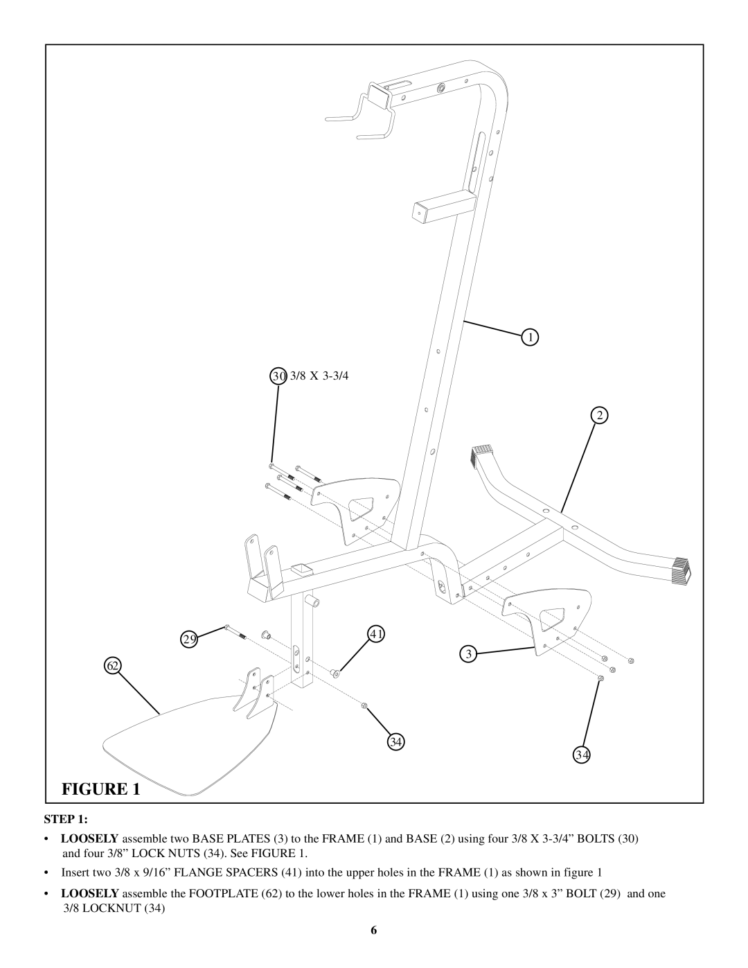
FIGURE 1 |
|
STEP 1:
•LOOSELY assemble two BASE PLATES (3) to the FRAME (1) and BASE (2) using four 3/8 X
•Insert two 3/8 x 9/16” FLANGE SPACERS (41) into the upper holes in the FRAME (1) as shown in figure 1
•LOOSELY assemble the FOOTPLATE (62) to the lower holes in the FRAME (1) using one 3/8 x 3” BOLT (29) and one 3/8 LOCKNUT (34)
6