16 |
|
|
| 34 LOW | 25 |
| HEIGHT | |
|
| |
32 | 26 |
|
20 |
| |
|
| |
32 |
|
|
1/2 X |
|
|
FIGURE 6 |
|
|
STEP 6:
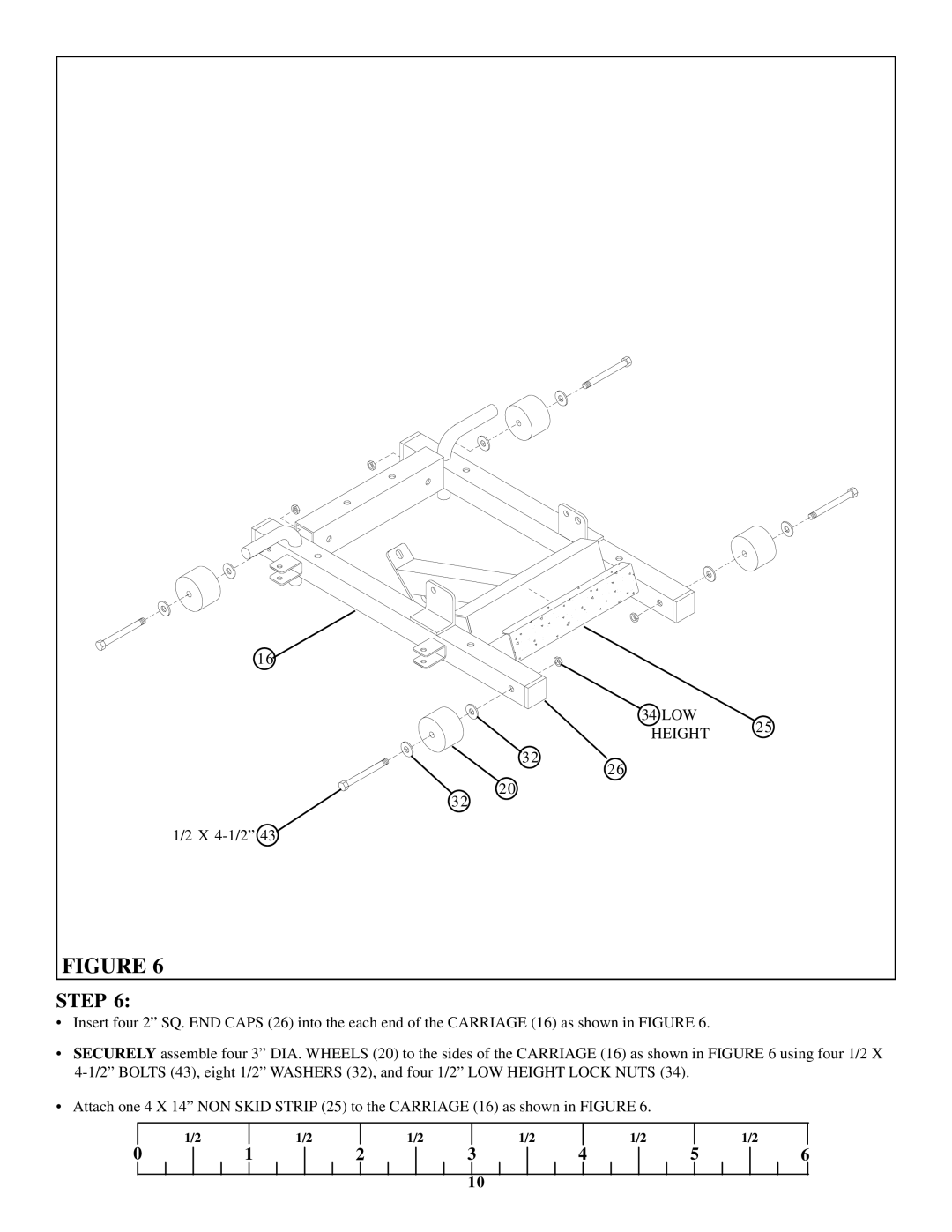
•Insert four 2” SQ. END CAPS (26) into the each end of the CARRIAGE (16) as shown in FIGURE 6.
•SECURELY assemble four 3” DIA. WHEELS (20) to the sides of the CARRIAGE (16) as shown in FIGURE 6 using four 1/2 X
•Attach one 4 X 14” NON SKID STRIP (25) to the CARRIAGE (16) as shown in FIGURE 6.
| 1/2 |
| 1/2 |
| 1/2 |
| 1/2 |
| 1/2 |
|
| 1/2 |
0 | 1 | 2 | 3 | 4 | 5 | 6 | ||||||
10
