| 1/2 X 4” 42 | |
| 11 | |
| 12 | |
| 47 | |
| 1/2 X 4” 42 | |
| 33 | |
| 2 | |
| 1 | |
SECURELYTIGHTEN |
| |
HANDLES BOTH SIDES | 33 | |
FIGURE 4 | ||
|
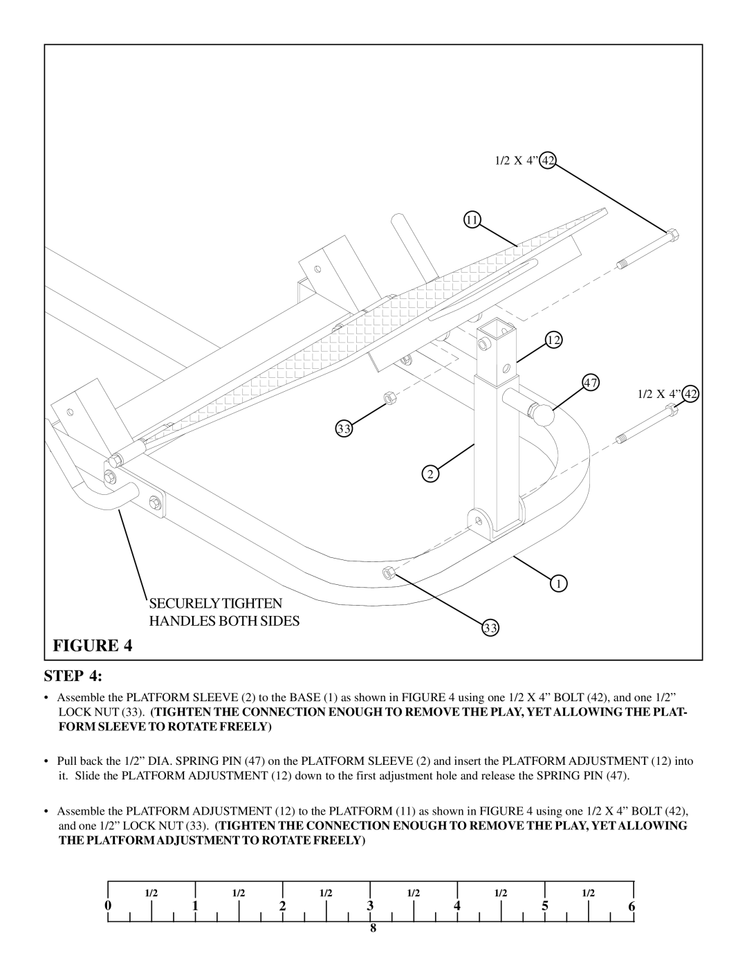
STEP 4:
•Assemble the PLATFORM SLEEVE (2) to the BASE (1) as shown in FIGURE 4 using one 1/2 X 4” BOLT (42), and one 1/2”
LOCK NUT (33). (TIGHTEN THE CONNECTION ENOUGH TO REMOVE THE PLAY, YET ALLOWING THE PLAT-
FORM SLEEVE TO ROTATE FREELY)
•Pull back the 1/2” DIA. SPRING PIN (47) on the PLATFORM SLEEVE (2) and insert the PLATFORM ADJUSTMENT (12) into it. Slide the PLATFORM ADJUSTMENT (12) down to the first adjustment hole and release the SPRING PIN (47).
•Assemble the PLATFORM ADJUSTMENT (12) to the PLATFORM (11) as shown in FIGURE 4 using one 1/2 X 4” BOLT (42), and one 1/2” LOCK NUT (33). (TIGHTEN THE CONNECTION ENOUGH TO REMOVE THE PLAY, YET ALLOWING
THE PLATFORM ADJUSTMENT TO ROTATE FREELY)
| 1/2 |
| 1/2 |
| 1/2 |
| 1/2 |
| 1/2 |
|
| 1/2 |
0 | 1 | 2 | 3 | 4 | 5 | 6 | ||||||
8