7975 specifications
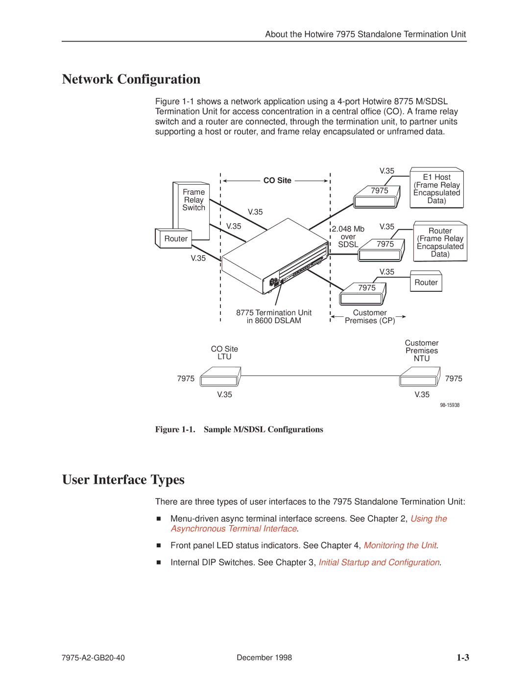
The Paradyne 7975 is a robust and versatile product that has made significant strides in the realm of data communications. This device primarily facilitates high-speed data transmission, leveraging advanced technologies designed to optimize performance and reliability. One of its standout features is its ability to handle both analog and digital signals, making it an essential tool for various networking environments.One of the key technologies employed in the Paradyne 7975 is the use of digital signal processing (DSP). This technology enhances the quality of signals transmitted over long distances, reducing the impact of noise and other interferences that can degrade performance. The integration of DSP allows for improved error correction techniques, ensuring data integrity during transmission.
Another notable feature of the Paradyne 7975 is its compatibility with a range of communication protocols. This inclusivity allows users to connect the device seamlessly with existing infrastructure, facilitating a smooth transition to higher data rates without the need for extensive upgrades. The product supports both T1 and E1 lines, catering to various network structures and requirements.
In terms of performance, the Paradyne 7975 boasts data rates of up to 2.048 Mbps for E1 and 1.544 Mbps for T1, allowing for efficient bandwidth utilization. Its architecture is designed for scalability, enabling businesses to expand their networks without encountering significant bottlenecks. Additionally, the device features built-in diagnostics and monitoring capabilities, which provide administrators with real-time insights into network performance and health.
The physical design of the Paradyne 7975 is also noteworthy. It typically comes in a compact form factor that can easily fit into standard telecommunications racks, making it a space-saving solution for data centers and offices. Its rugged construction ensures longevity and reliability, even in demanding environments.
Moreover, the device includes an intuitive user interface that simplifies configuration and maintenance processes, reducing the overall burden on IT staff. Additionally, its adaptive capabilities enable the device to automatically adjust to varying line conditions, ensuring optimal performance at all times.
Overall, the Paradyne 7975 stands out as a comprehensive solution for businesses seeking to enhance their data communication infrastructures. With its advanced features, compatibility, and user-friendly design, it continues to be a preferred choice for organizations looking to leverage high-speed data transmission technologies.

