4.3.1 TERMINAL INTERFACE CONNECTION
The RS-232 versions of the Model 1018RC use a DB-25 female to connect the terminal interface to your computing hardware. It is pinned according to the RS-232C/V.24 and EIA-530 interface standards. For specific interface pin-outs, please refer to the diagram in Appendix D of this manual.
The EIA-561 versions of the Model 1018RC use a 10 pin RJ-45 to connect the terminal interface to your computing hardware. It is pinned according to the EIA-561 DCE interface standard. For specific interface pin-outs, please refer to the diagram in Appendix D of this manual.
Notice! Any terminal cable connected to the Patton Model 1018RC must be shielded cable, and the outer shield must be 360 degree bonded–at both ends–to a metal or metalized backshell.
4.3.2 TWISTED PAIR CONNECTION
The Model 1018RC operates over two twisted pair. In all applications, the twisted pair wire must be 26 AWG or thicker, unconditioned, dry, metallic wire. Both shielded and unshielded wire yield favorable results. Note: The Model 1018RC can only communicate in a closed data circuit, and is compatible with the following Patton short hauls: Model 1018RC, Model 1018, Model 1080A, Model 1080ARC. Dial-up analog circuits, such as those used with a standard Hayes-type modem, are not acceptable. For further information about acceptable wire grades, please refer to the diagrams in Appendix B.
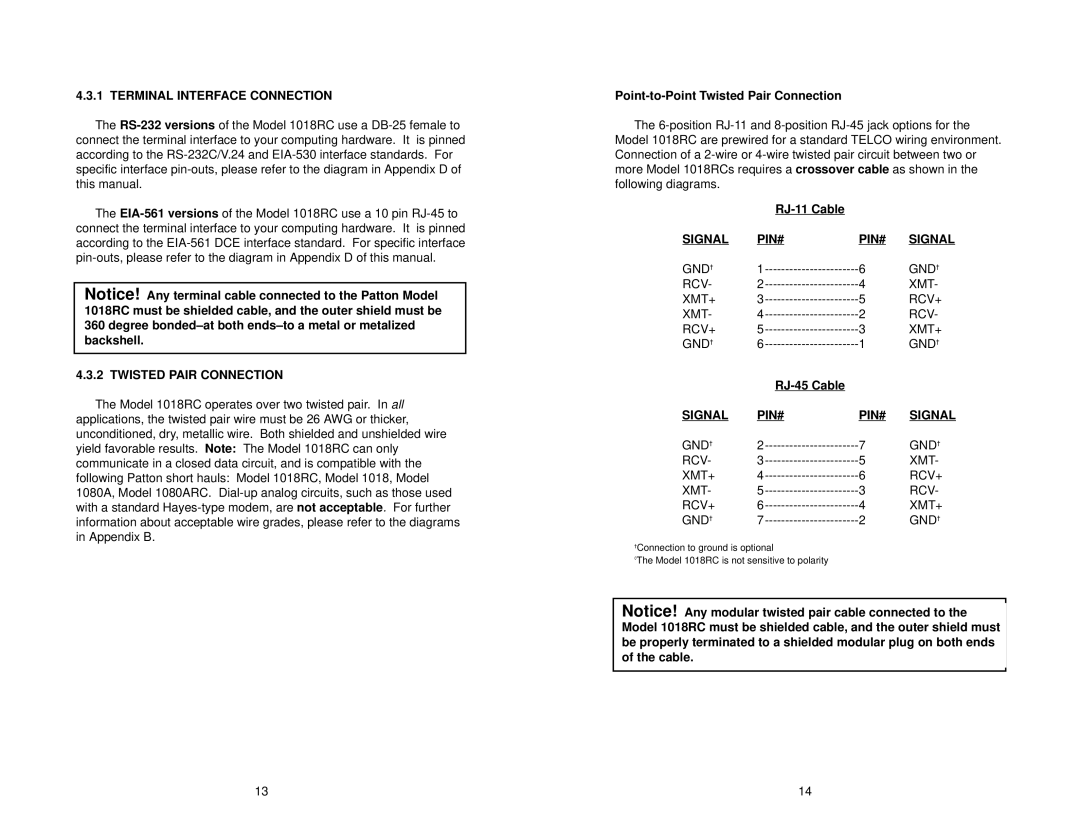
Point-to-Point Twisted Pair Connection
The 6-position RJ-11 and 8-position RJ-45 jack options for the Model 1018RC are prewired for a standard TELCO wiring environment. Connection of a 2-wire or 4-wire twisted pair circuit between two or more Model 1018RCs requires a crossover cable as shown in the following diagrams.
| RJ-11 Cable | | |
SIGNAL | PIN# | PIN# | SIGNAL |
GND† | 1----------------------- | 6 | GND† |
RCV- | 2----------------------- | 4 | XMT- |
XMT+ | 3----------------------- | 5 | RCV+ |
XMT- | 4----------------------- | 2 | RCV- |
RCV+ | 5----------------------- | 3 | XMT+ |
GND† | 6----------------------- | 1 | GND† |
| RJ-45 Cable | | |
SIGNAL | PIN# | PIN# | SIGNAL |
GND† | 2----------------------- | 7 | GND† |
RCV- | 3----------------------- | 5 | XMT- |
XMT+ | 4----------------------- | 6 | RCV+ |
XMT- | 5----------------------- | 3 | RCV- |
RCV+ | 6----------------------- | 4 | XMT+ |
GND† | 7----------------------- | 2 | GND† |
†Connection to ground is optional
◊The Model 1018RC is not sensitive to polarity
Notice! Any modular twisted pair cable connected to the Model 1018RC must be shielded cable, and the outer shield must be properly terminated to a shielded modular plug on both ends of the cable.