S2-1: V.54 Disable
The setting for switch
Setting | ||
On | V.54 | Test Disabled |
Off | V.54 | Test Enabled (Normal) |
S2-2: Carrier Control
The setting for switch
Setting | |
On | Controlled by DTR |
Off | Constantly ON |
S2-3 and S2-4: Link Clocking Method
Switches
Setting | ||
On | On | Internal |
|
| No other valid settings |
S2-5 through S2-7: Asynchronous Data Rate Setting
Switches
Setting | ||||
Off | Off | Off | 1.2 | Kbps |
Off | Off | On | 2.4 | Kbps |
Off | On | Off | 4.8 | Kbps |
Off | On | On | 9.6 | Kbps |
On | Off | Off | 19.2 | Kbps |
On | Off | On | 28.8 | Kbps |
On | On | Off | 38.4 | Kbps |
On | On | On | 57.6 Kbps | |
S2-8: Microprocessor Reset
The setting for switch
Setting | |
On | Reset Mode |
Off | Normal Operating Mode |
3.1.3 CONFIGURATION JUMPERS
Configuration jumpers (JP1 through JP4) on the Model 1018RC Function Card are primarily intended for factory configuration of the RS- 232 interface. We recommended that you do not
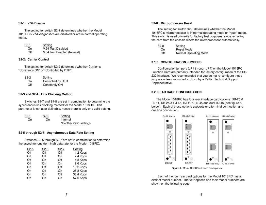
3.2 REAR CARD CONFIGURATION
The Model 1018RC has four rear interface card options:
|
|
|
|
|
|
|
|
|
|
|
|
|
|
|
|
|
|
|
|
|
|
|
|
|
|
|
|
|
|
|
|
|
|
|
|
|
|
|
|
|
|
|
|
|
|
|
|
|
|
|
|
|
|
|
|
|
|
|
|
|
|
|
|
|
|
|
|
|
|
|
|
|
|
|
|
|
|
|
|
|
|
|
|
|
|
|
|
|
|
|
|
|
|
|
|
|
|
|
|
|
|
|
|
|
|
|
|
|
|
|
|
|
|
|
|
|
|
|
|
|
|
|
|
|
|
|
|
|
|
|
|
|
|
|
|
|
|
|
|
|
|
|
|
|
|
|
|
|
|
|
|
|
|
|
|
|
|
|
|
|
|
|
|
|
|
|
|
|
|
|
|
|
|
|
|
|
|
|
|
|
|
|
|
|
|
|
|
|
|
|
|
|
|
|
|
|
|
|
|
|
|
|
|
|
|
|
|
|
|
Figure 5. Model 1018RC interface card options
Each of the four rear card options for the Model 1018RC has a distinct model number. The four options and their model numbers are shown on the following page.
7 | 8 |