data stream are detected. The receiver recognizes these special violations and decodes them as zeros. This method enables the network to meet minimum pulse density requirements. Use HDB3 unless AMI is required in your application.

Alternate Mark Inversion (AMI): AMI defines a pulse as a Òmark,Ó a binary one, as opposed to a zero. In an E1 Network con- nection, signals are transmitted as a sequence of ones and zeros. Ones are sent as pulses, and zeros are sent as spaces, i.e., no pulse. Every other pulse is inverted from the previous pulse in polarity, so that the signal can be effectively transmitted. This means, however, that a long sequence of zeros in the data stream will cause problems, since the modem receiving the signal relies on the signal to recover the 2.048 Mbps clock.

If you must use AMI, ensure that the data terminal equipment con- nected to the unit provides a minimally acceptable pulse density. For this reason, there are advantages to using HDB3 instead. AMI coding does not inherently account for ones density. To meet this requirement, ensure that the data inherently meets pulse density requirements.

S3

S4

DTE Line Coding

Off

Off

HDB3

Off

On

Internal use only

On

Off

Internal use only

On

On

AMI

Switches S5 through S8: Reserved

Switches S5 through S8 are reserved for future applications and should be set to OFF.

3.1.2 Select RJ-48C or BNC Connectors

The Model 1193 is shipped configured for use with a BNC connec- tion to the G.703/G.704 Network. If your Network connection is using BNC, skip this section.

Jumper Configuration

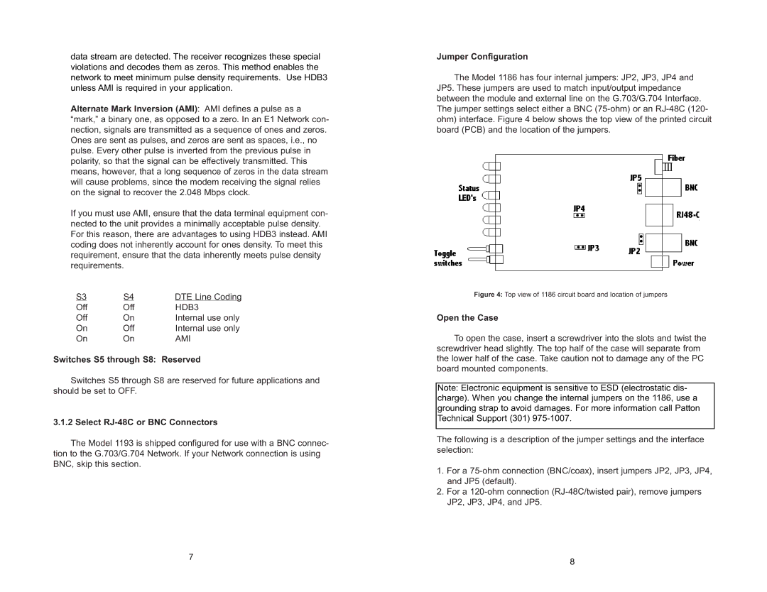
The Model 1186 has four internal jumpers: JP2, JP3, JP4 and JP5. These jumpers are used to match input/output impedance between the module and external line on the G.703/G.704 Interface. The jumper settings select either a BNC (75-ohm) or an RJ-48C (120- ohm) interface. Figure 4 below shows the top view of the printed circuit board (PCB) and the location of the jumpers.

Figure 4: Top view of 1186 circuit board and location of jumpers

Open the Case

To open the case, insert a screwdriver into the slots and twist the screwdriver head slightly. The top half of the case will separate from the lower half of the case. Take caution not to damage any of the PC board mounted components.

Note: Electronic equipment is sensitive to ESD (electrostatic dis- charge). When you change the internal jumpers on the 1186, use a grounding strap to avoid damages. For more information call Patton Technical Support (301) 975-1007.

The following is a description of the jumper settings and the interface selection:

1.For a 75-ohm connection (BNC/coax), insert jumpers JP2, JP3, JP4, and JP5 (default).

2.For a 120-ohm connection (RJ-48C/twisted pair), remove jumpers JP2, JP3, JP4, and JP5.

7

8


Page 5
Image 5
Patton electronic 1186 user manual Switches S5 through S8 Reserved, Select RJ-48C or BNC Connectors, Jumper Configuration

1186 specifications

The Patton Electronics 1186 is a cutting-edge device tailored for efficient transmission and reliable connectivity in various communication systems. Known for its robust performance, the 1186 primarily serves as a T1/E1 multiplexer that seamlessly integrates multiple telecommunication lines into a single, coherent channel. This advanced multiplexer is engineered for both reliability and flexibility, making it an essential tool for businesses looking to enhance their communication infrastructure.

One of the standout features of the Patton 1186 is its ability to support multiple digital communication protocols, including T1 and E1 lines. It can efficiently aggregate voice and data traffic, providing a versatile solution for businesses that require high-quality voice services along with data transmission. This capability is vital for companies that rely on voice over IP (VoIP) communications while maintaining a robust data network.

In terms of technology, the 1186 employs advanced digital signal processing to ensure the highest level of signal integrity. This results in minimal latency and optimal bandwidth utilization, crucial for maintaining quality in voice and data transmission. Additionally, the device supports various channelization options, allowing users to configure it according to their specific requirements, whether for voice, video, or data services.

Another characteristic that sets the Patton 1186 apart is its user-friendly interface. The device is equipped with an intuitive management system that simplifies configuration and troubleshooting. This ease of use is complemented by comprehensive diagnostic tools that help network administrators monitor performance and quickly address any issues that may arise.

Reliability is a hallmark of the Patton 1186, featuring robust physical construction that withstands harsh operating environments. Its longevity is further bolstered by built-in redundancy features, ensuring continuous operation even in the event of hardware failures. The device is designed for quick deployment, minimizing downtime during installation.

In summary, the Patton Electronics 1186 is an exemplary T1/E1 multiplexer that offers a unique combination of versatility, reliability, and user-friendliness. With its support for various communication protocols, advanced digital processing technology, and robust build, it stands as an ideal choice for businesses seeking to modernize their communication systems. Its ability to aggregate voice and data streams makes it an integral component of any modern telecommunication setup, paving the way for enhanced connectivity and operational efficiency.