Manuals
/
Patton electronic
/
Computer Equipment
/
Power Supply
Patton electronic
2073RC
user manual
Orientation of Interface Card Straps
Models:
2073RC
1
11
28
28
Download
28 pages
21.55 Kb
8
9
10
11
12
13
14
15
Install
LED Status Indicators
Connecting to a DTE Device
Warranty
Configuration
Loop V.54 & Telco Diagnostics
Service
Features
Page 11
Image 11
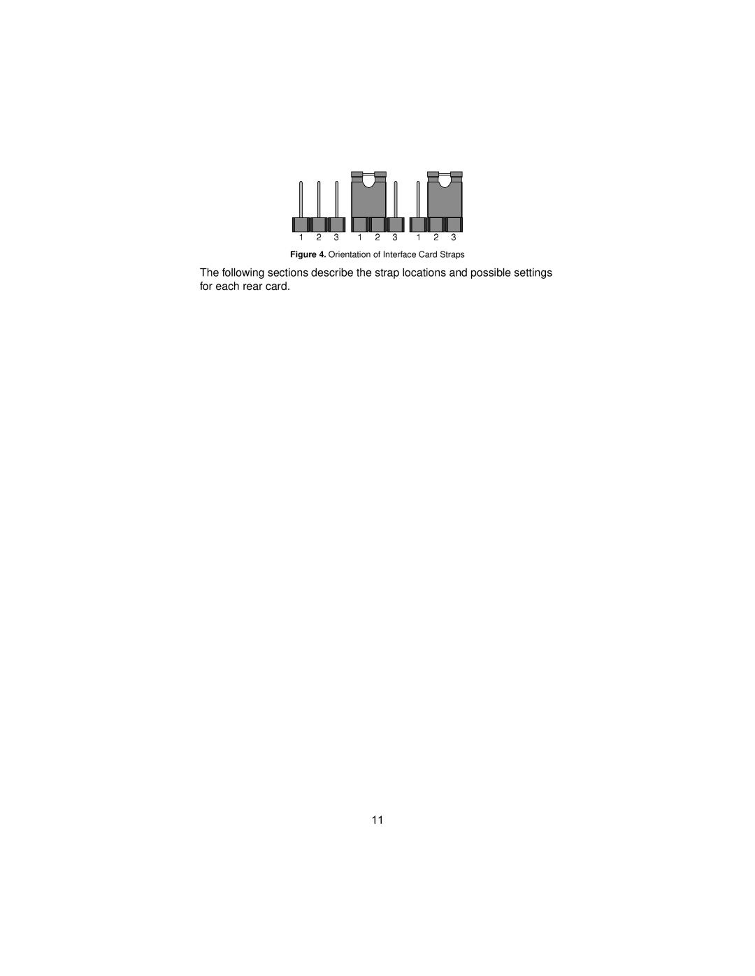
Figure 4.
Orientation of Interface Card Straps
The following sections describe the strap locations and possible settings for each rear card.
11
Page 10
Page 12
Page 11
Image 11
Page 10
Page 12
Contents
User Manual
Contents
Interface Pin Assignment
CE Notice
Warranty Information
Radio and TV Interference
UTC-5, Monday through Friday
Service
Tel +1 301 Email support@patton.com
Description
Features
General Information
Model 2073RC top view showing location of DIP switches
Configuration
OFF
Configuring the Front Interface Card
SW3-4 Description
Switches SW3-5 Front panel switch enabled/disabled
Switch SW3-4 Response to Remote digital RDL Loopback
SW3-6 Activation Description
Model 2073RC Series interface card options
Configuring the Rear Interface Card
Orientation of Interface Card Straps
Strap Function Position 1&2 Position 2&3
Model 1001RCM13448C Strap Settings
Position Description
Model 1001RCM11548C Strap Settings
Frgnd & Sgnd Pin
IM2RC/A, rear panel options
Model IM2RC/IA 10Base-T Ethernet Rear Card
No connection
Page
Model 1001R14 Rack Chassis
Installation
Rack Power Supply
Connecting to a DCE Device
Powering up your 1001R14 rack
Installing the Model 2073RC Into the Chassis
Connecting to a DTE Device
NetLink-E1 twisted-pair interface
Connecting to a G.703/64 Kbps Network
LED Descriptions
Operation
Operating Local Loopback LLB
Loop V.54 & Telco Diagnostics
Operating Remote Digital Loopback RDL
Bit Error Rate V.52 Diagnostics
Temperature Range
Diagnostics
LED Status Indicators
Connectors
Appendix B
Interface 34F Female Connector DCE Configuration Pin # Signal
Frame Ground
Page
Copyright Patton Electronics Company All Rights Reserved
Top
Page
Image
Contents